Welding robot

A welding robot and welding torch technology, applied in welding equipment, auxiliary welding equipment, welding/cutting auxiliary equipment, etc., can solve the problems that the fine adjustment of the welding torch position cannot be realized, and the welding robot cannot meet the welding needs, so as to improve welding efficiency and reduce Center of gravity, smooth and reliable sliding effect

Active Publication Date: 2017-05-10
颍上县祥盛建设管理有限公司
View PDF6 Cites 4 Cited by
  • Summary
  • Abstract
  • Description
  • Claims
  • Application Information

AI Technical Summary

Problems solved by technology

[0003] Although most of the existing welding robots can realize the three-way adjustment of the welding torch in the X direction, Y direction and Z direction, they cannot realize the fine adjustment of the position of the welding torch. In this way, when welding small batches of parts, existing of welding robots cannot meet welding needs

Method used


Image

  • Welding robot
  • Welding robot
  • Welding robot

Examples


Embodiment Construction

[0029] In order to make the object, technical solution and advantages of the present invention clearer, the implementation manner of the present invention will be further described in detail below in conjunction with the accompanying drawings.

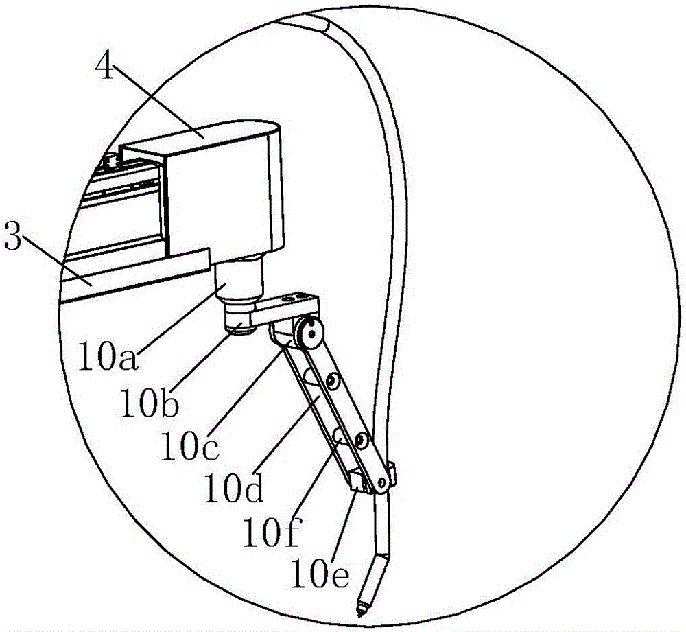
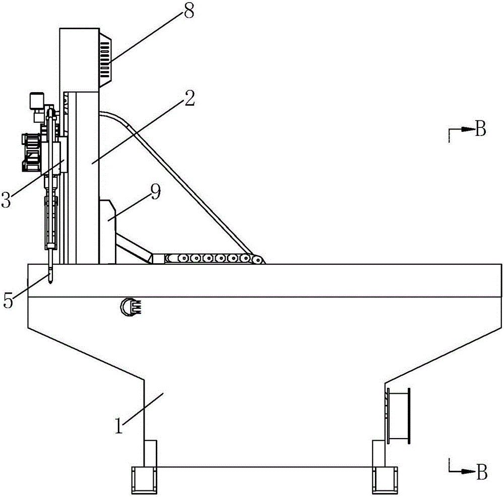
[0030] Such as figure 1 As shown, a welding robot provided in this embodiment includes a base 1, a column 2, a beam 3, a welding gun mount 4, a welding gun 5 and a controller 6, and the controller 6 is installed on the bottom of the base 1 , the column 2 is slidably installed on the top surface of the base 1 along the X-axis direction, the beam 3 is slidably installed on the column 2 along the Z-axis direction, and the welding torch mounting seat 4 is slid along the Y-axis direction Installed on the crossbeam 3, the Y-direction drive motor assembly 7 for driving the welding torch mount 4 to slide is installed on the crossbeam 3, and the upper end of the column 2 is provided with a Z-direction drive for driving the slide of the crossbea...


PUM


Abstract

The invention relates to a welding robot which comprises a controller. The controller is arranged at the bottom of a base. A stand column is arranged on the top face of the base in a sliding manner in the X-axis direction. A cross beam is arranged on the stand column in a sliding manner in the Z-axis direction. A welding gun installation seat is arranged on the cross beam in a sliding manner in the Y-axis direction. A Y-direction drive motor assembly is arranged on the cross beam. A Z-direction drive motor assembly is arranged at the upper end of the stand column. An X-direction drive motor assembly is arranged at the lower end of the stand column. The invention further comprises a rotating motor which is installed on the welding gun installation seat. The output shaft of the rotating motor is connected with a rotating arm, and the other end of the rotating arm is connected with the side wall of an angle positioning disc. One ends of two angle adjusting connecting plates are clamped to the two ends of the angle positioning disc. The other ends of the two angle adjusting connecting plates are connected with a welding gun clamping piece. A welding gun is clamped and installed in the welding gun clamping piece. The X-direction drive motor assembly, the Y-direction drive motor assembly, the Z-direction drive motor assembly and the rotating motor are connected with the controller. The welding robot is suitable for welding small-batch parts.

Description

technical field [0001] The invention relates to the field of welding, in particular to a welding robot. Background technique [0002] At present, in the welding process, there are a wide variety of welding robots according to different welding methods. Automatic welding has made great progress in solving the quality and efficiency of manual welding, but the existing welding robots are not suitable for some small batches of parts When welding, there are the following problems: [0003] Although most of the existing welding robots can realize the three-way adjustment of the welding torch in the X direction, Y direction and Z direction, they cannot realize the fine adjustment of the position of the welding torch. In this way, when welding small batches of parts, the existing The welding robot cannot meet the welding needs. Contents of the invention [0004] The object of the present invention is to provide a welding robot in order to overcome the disadvantages of the above-...

Claims


Application Information

Patent Timeline
Patent Type & Authority Applications(China)
IPC IPC(8): B23K37/02B23K37/00
CPCB23K37/00B23K37/006B23K37/02
Inventor 陈和平黄荣腾王晓晖
Owner 颍上县祥盛建设管理有限公司
Why Eureka
Try Eureka