Wire drawing device of luggage rack cover plate

A luggage rack and wire drawing technology, which is used in grinding/polishing safety devices, grinding workpiece supports, machine tools suitable for grinding workpiece planes, etc., can solve problems such as low insertion efficiency, corrosive cleaning fluid, and complicated processes , to avoid product stress, avoid manual drying, and ensure accuracy

Active Publication Date: 2017-05-10
NINGBO MINTH AUTOMOTIVE PARTS RES&DEV CO LTD
View PDF5 Cites 4 Cited by
  • Summary
  • Abstract
  • Description
  • Claims
  • Application Information

AI Technical Summary

Problems solved by technology

The disadvantage of method 1 is that the insertion efficiency is low and it is easy to arch; the disadvantage of method 2 is that it needs to be inserted one by one, and the efficiency is also low; at the same time, the employees of the two methods need to be stained with cleaning fluid for drawing, and the cleaning fluid is corrosive , which will affect the health of employees, so the present invention designs a fully automatic wire drawing tool to automatically complete the wire drawing process. Here, the wire drawing device is mainly an important part of the whole wire drawing tool. Complicated, it is easy to cause damage to the product during wire drawing, which affects the work efficiency of the entire wire drawing tool

Method used


Image

  • Wire drawing device of luggage rack cover plate
  • Wire drawing device of luggage rack cover plate
  • Wire drawing device of luggage rack cover plate

Examples


Embodiment Construction

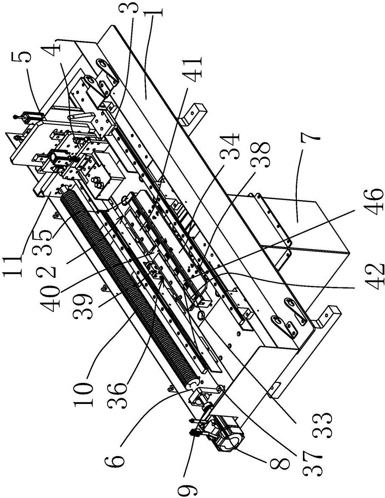
[0027] The following are specific embodiments of the present invention and in conjunction with the accompanying drawings, the technical solutions of the present invention are further described, but the present invention is not limited to these embodiments.

[0028] In the figure, bottom plate 1; placement positioning component 2; slide rail slider component 3; wire drawing component 4; cleaning component 5; sliding power component 6; waste material funnel 7; servo motor 8; Plate 11; cleaning fixed plate 12; cleaning lifting cylinder 13; cleaning bottom plate 14; ; Cleaning cloth 21; Nozzle fixing plate 22; Cleaning water spraying parts 23; Drawing lifting cylinder 24; Drawing lifting plate 25; Drawing floating slider slide rail parts 26; ;Water jet fixed plate 30; drawing water jet parts 31; air blow parts 32; main clamp body 33; positioning block 34; Positioning and clamping slide rail pad 38; positioning cylinder 39; clamping push plate 40; pressing guide block 41; pressing...


PUM


Abstract

The invention belongs to the technical field of automobile accessory manufacturing tools and provides a wire drawing device of a luggage rack cover plate. The device comprises a bottom plate, a placement positioning assembly, a sliding rail and slider assembly, a wire drawing component, a cleaning component and a sliding power component. The bottom plate is located at the bottom, the sliding power component is arranged on one side of the bottom plate and connected with the sliding rail and slider assembly, the sliding power component drives the sliding rail and slider assembly to move, and the sliding rail and slider assembly drives the wire drawing component and the cleaning component which are combined together to move back and forth on the surface of the placed cover plate. The wire drawing device has the advantages the advantages that wire drawing stress is made uniform by using a cylinder floating mechanism, and quality can still be ensured under the condition that a wire drawing brush is abraded; by the adoption of an automatic cleaning device, manual wiping is avoided; a detergent flushing device is used, so wire drawing disorder caused by particles is avoided; an automatic air blowing device is used so that detergent can be blown dry directly, and the situation that the detergent is wiped dry manually is avoided.

Description

technical field [0001] The invention belongs to the technical field of manufacturing tooling for auto parts, and relates to a manufacturing tooling for a luggage rack, in particular to a wire drawing device for a luggage rack cover. Background technique [0002] The fixing method of the car luggage rack products is screwed from the top down, which determines that the cover plate is required to cover the upper hole of the luggage rack, and the surface treatment of these cover plates must be consistent with the luggage rack. When the luggage rack is brushed, the cover plate must also be brushed, and the silk pattern direction is uniform and uniform. Each luggage rack usually has 4 covers, such as figure 1 and figure 2 As shown, the cover plate 46 is divided into a large cover plate and a small cover plate. Two methods are currently used for the wire drawing of the existing cover plate: 1. longitudinal insertion and clamping, manual wire drawing; 2, lateral tightening, manua...

Claims


Application Information

Patent Timeline
IPC IPC(8): B24B7/10B24B41/06B24B55/00B24B55/02B24B55/06
CPCB24B7/10B24B41/06B24B55/00B24B55/02B24B55/06
Inventor 胡剑英
Owner NINGBO MINTH AUTOMOTIVE PARTS RES&DEV CO LTD
Why Eureka
Try Eureka