Upper and lower shell connecting structure and printer comprising same

A connection structure and rotating connection technology, applied in printing devices, printing, etc., can solve problems such as unfavorable operation, complicated assembly, and increased product height and width, so as to avoid misoperation, enhance reliability, and eliminate inability to lock in place Effect

Active Publication Date: 2017-05-10
CHONGQING PINSHENG TECH CO LTD
View PDF12 Cites 5 Cited by
  • Summary
  • Abstract
  • Description
  • Claims
  • Application Information

AI Technical Summary

Problems solved by technology

Even if the resistance structure is designed, it is mostly a friction resistance structure, which not only has a large number of parts, but also makes assembly more complicated, and the larger volume will increase the height and width of the product
[0004] The shafts of the upper and lower shells are close to the position of the buckle. When the cover is opened to pick and place labels, there will be interference in the vertical direction, which is not conducive to operation. The outer structure of the shaft of the upper shell will be transferred into the lower shell when the cover is opened, so that the height of the product is high. It will increase, complicate the structure and affect the appearance
[0005] In traditional printers, the shift block that drives the upper casing to open is usually installed through a torsion spring structure, which is inconvenient to assemble and low in production efficiency. At the same time, the opening structure requires a high space for the upper casing. If the space is too small, it cannot be installed, and if the space is too large, it will increase Printer size
In order to ensure that the printer can only print when it is closed, the detection switch is usually set in the positive direction of the upper and lower shells in the prior art. Due to the problem of the setting position, the detection switch has been detected and can be printed when the upper shell is not fully closed, so During the printing process, the upper case may pop open suddenly or the printing is not clear, etc.

Method used


Image

  • Upper and lower shell connecting structure and printer comprising same
  • Upper and lower shell connecting structure and printer comprising same
  • Upper and lower shell connecting structure and printer comprising same

Examples


Embodiment

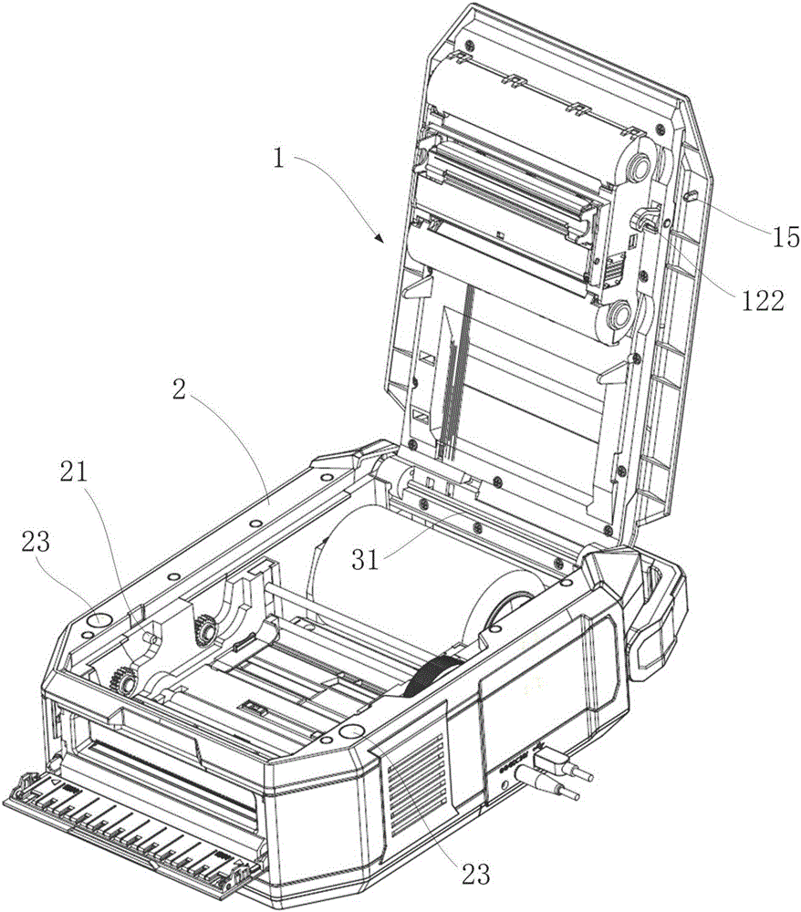
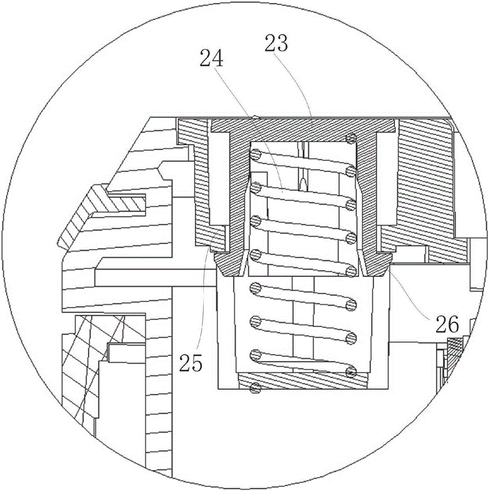
[0075] Such as figure 1 , figure 2and Figure 5 As shown, an upper and lower shell connection structure includes an upper shell assembly 1 and a lower shell assembly 2 that are rotatably connected, and a cover locking mechanism is arranged between the upper shell assembly 1 and the lower shell assembly 2, and the upper shell assembly 1 and the lower shell assembly There is also an auxiliary ejection mechanism between the components 2. When the cover is opened, after the cover locking mechanism is unlocked, the auxiliary ejection mechanism will push the upper shell component 1 out so that there is a gap between it and the lower shell component 2, which is convenient Put your fingers in to open the upper case assembly 1 .

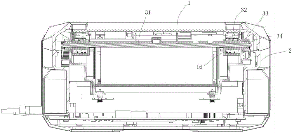
[0076] Further as shown in the figure, the upper shell assembly 1 and the rear end of the lower shell assembly 2 are rotatably connected by a torsion spring 32 and a rotating shaft 31, and accommodation grooves 16 are provided on both sides of the rear end...


PUM


Abstract

The invention provides an upper and lower shell connecting structure and a printer comprising the same. The upper and lower shell connecting structure comprises an upper shell component and a lower shell component which are connected rotationally. A cover locking mechanism is arranged between the upper shell component and the lower shell component. An auxiliary push-out mechanism is also arranged between the upper shell component and the lower shell component. When a cover is being opened, the auxiliary push-out mechanism pushes the upper shell component out so there is a gap between the upper shell component and the lower shell component. The back ends of the upper shell component and the lower shell component are connected rotationally through a torsion spring and a rotating shaft. The cover locking mechanism is disposed in the front part of the upper shell component and the lower shell component. The auxiliary push-out mechanism is close to the cover locking mechanism. After the cover locking mechanism is opened, the auxiliary push-out mechanism pushes out the end of the upper shell component away from the hinge joint to separate the upper shell component from the lower shell component so that an operator can extend a finger in to open the upper shell component for carbon ribbon or label installation. Through the torsion spring and the auxiliary push-out mechanism, the problem that a printer may be damaged or an operator may be injured when the torsion of the torsion spring is too big or small is avoided.

Description

technical field [0001] The invention belongs to the technical field of printers, and in particular relates to a connecting structure of upper and lower shells and a printer thereof. Background technique [0002] Label printer is a device that prints barcode, two-dimensional code, graphics, text and other image information on labels by means of thermal and thermal transfer printing. It is widely used in POS terminal systems, banking systems, medical instruments and other fields. [0003] In the existing connection structure of the upper and lower shells of the whole machine, the upper and lower shells directly open and close the cover through the relationship between the shaft and the hole, and there is no hook to engage and fix it. There is no resistance mechanism at the rotating shaft, which is easy to damage the product and damage the use when closing the cover. Or; because the upper and lower shells do not have hooks, they will shake when moving or the upper shell will ro...

Claims


Application Information

Patent Timeline
Patent Type & Authority Applications(China)
IPC IPC(8): B41J29/13
CPCB41J29/13
Inventor 庞静
Owner CHONGQING PINSHENG TECH CO LTD
Why Eureka
Try Eureka