Compressor

A compressor and thrust technology, applied in the field of compressors, can solve problems such as friction and wear, and achieve the effects of simplifying assembly, solving the problem of stator and rotor clearance, and improving assembly accuracy

Active Publication Date: 2016-03-02
SHANGHAI HITACHI ELECTRICAL APPLIANCES CO LTD
View PDF6 Cites 3 Cited by
  • Summary
  • Abstract
  • Description
  • Claims
  • Application Information

AI Technical Summary

Problems solved by technology

[0011] In view of the defects in the prior art, the purpose of the present invention is to provide a compressor that can not only meet the wear requirements of the friction pair formed by the main bearing and the crankshaft, but also meet the welding requirements of the bearing and the upper and lower shell covers, and at the same time reduce the The difficulty of processing; and solve the problem of friction and wear of the two friction surfaces, move the center of operation of the entire shaft system up to improve stability

Method used


Image

  • Compressor
  • Compressor
  • Compressor

Examples


no. 1 example

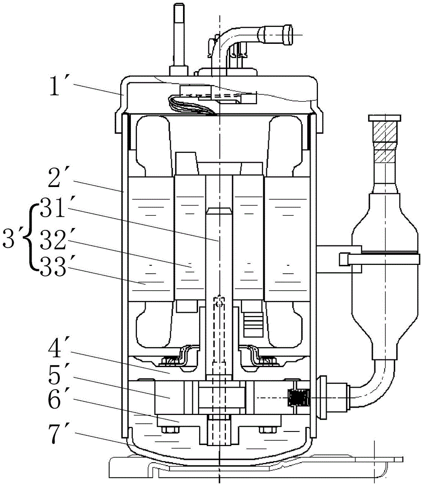
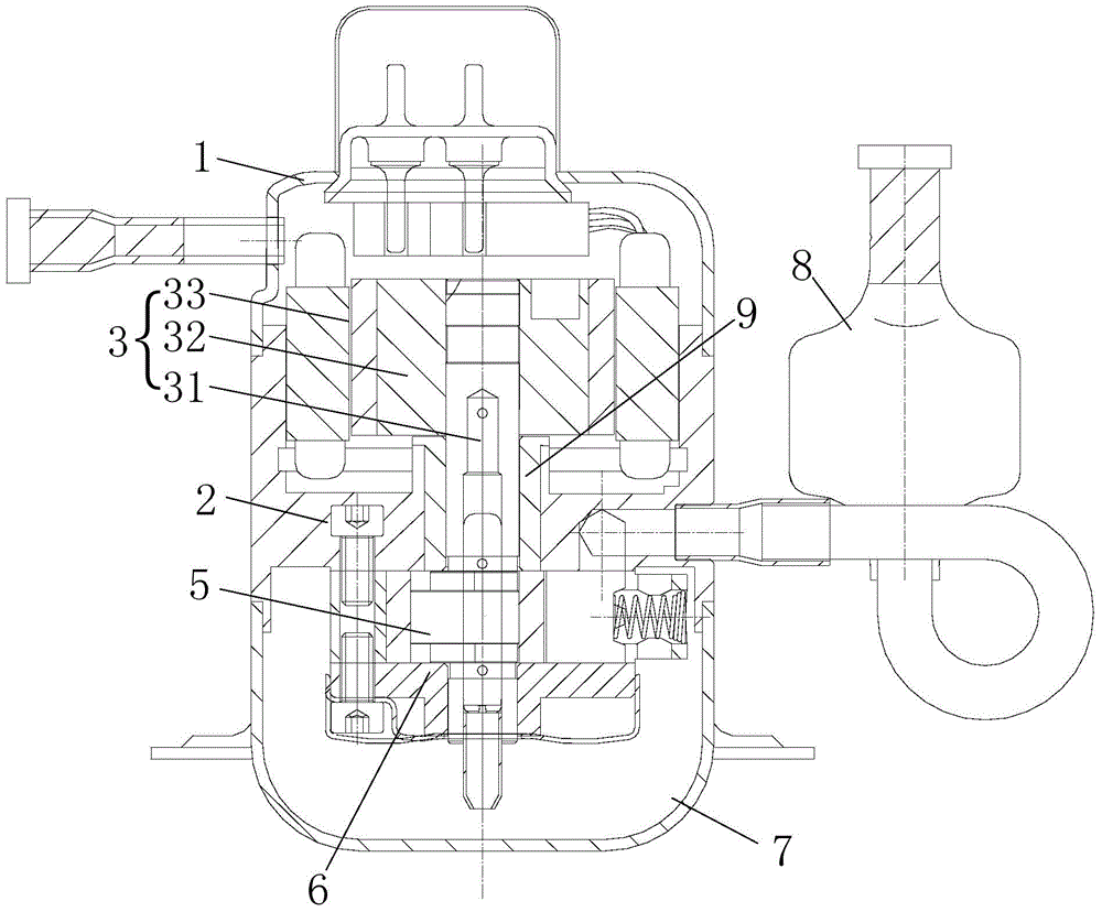
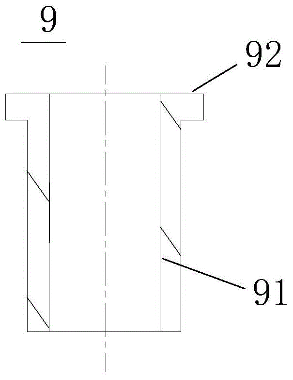
[0085] like figure 2 As shown, the compressor of the present invention includes: a housing; the motor 3 is accommodated in the upper space in the housing; the cylinder 5 is accommodated in the lower space in the housing; the crankshaft 31 has a long axis portion 311 and an eccentric portion 312 and short axis portion 313 (such as Figure 4 shown), the crankshaft 31 transmits the rotational force of the motor 3 to the cylinder 5 to compress the refrigerant; the first bearing assembly and the second bearing assembly together define the compression space with the cylinder 5 and support the crankshaft 31, wherein the first bearing assembly Including at least upper bearing 2 (ie main bearing) and thrust bushing 9, upper bearing 2 is located between motor 3 and cylinder 5, thrust bushing 9 has a crankshaft supporting part 91 and a thrust part 92 carrying crankshaft 31 (like image 3 shown); the second bearing assembly includes at least the lower bearing 6 (ie the auxiliary bearin...

no. 2 example

[0096] like Image 6 As shown, in a modification example, the outer edge of the thrust portion 92a of the thrust bushing 9a is bent downward to extend a flange portion 93a, and a thrust support piece 10 is added to be arranged on the flange portion 93a and the upper bearing 2 between the upper surfaces of the disc portion 21. The thrust bush 9a is still made of self-lubricating material, and other technical features are the same as those of the first embodiment, and will not be repeated here.

[0097] like Figure 7 As shown, compared with the first embodiment, the second embodiment improves the structure of the thrust bush 9a in order to better distribute the weight of the crankshaft 31 carried by the thrust bush 9a. Specifically, the inner hole of the crankshaft supporting portion 91a of the thrust bush 9a and the flange portion 93a can clamp the inner edge portion 25 of the upper bearing 2, so that the thrust bush 9a and the upper bearing 2 are more stable. And the thrus...


PUM


Abstract

The invention provides a compressor. A motor and an air cylinder are contained in a shell. A bent axle is provided with a long axle part, an eccentric part and a short axle part. The bent axle transmits rotation force of the motor to the air cylinder to compress refrigerant. Compression space is jointly defined by a first bearing assembly, a second bearing assembly and the air cylinder, and the bent axle is supported. The first bearing assembly comprises a main bearing located between the motor and the air cylinder, and a thrust bush. The main bearing is provided with a disc part with a through hole and an inner edge part protruding upwards from the inner circumference of the disc part. The material of the thrust bush is more resistant to abrasion than the material of the main bearing. The thrust bush is provided with a bent axle supporting part and a thrust part bearing the bent axle. The bent axle supporting part is located in the through hole of the main bearing and provided with an inner hole supporting the bent axle so as to be arranged on the long axle part of the bent axle in a sleeving manner. The thrust bush is additionally arranged at the main bearing of the compressor, and the problem of friction abrasion of two friction faces can be solved at a time through one-time pressing.

Description

technical field [0001] The invention relates to a compressor, in particular to a fully enclosed rolling rotor compressor. Background technique [0002] In general, a hermetic compressor includes a motor for generating a driving force in an inner space of a hermetically sealed case, and a compression part coupled to the motor for compressing refrigerant. Hermetic compressors can be classified into reciprocating compressors, scroll compressors, and rolling rotor compressors according to different refrigerant compression mechanisms. Reciprocating compressors, scroll compressors, and rolling rotor compressors all utilize the rotational force of an electric motor. [0003] The motor of the existing hermetic compressor utilizing rotational force has a crankshaft, and the rotational force of the motor is transmitted to the compression part through the crankshaft. figure 1 Shown is a structural schematic diagram of a rolling rotor compressor in the prior art. As shown in the figu...

Claims


Application Information

Patent Timeline
Patent Type & Authority Applications(China)
IPC IPC(8): F04C29/00
Inventor 刘杨
Owner SHANGHAI HITACHI ELECTRICAL APPLIANCES CO LTD
Why Eureka
Try Eureka