Compressor

A compressor and main bearing technology, applied in the field of compressors, can solve the problems of easy deformation due to heat, shorten the service life of the motor, serious wear, etc., and achieve the effect of solving the gap between the stator and rotor, reducing the processing difficulty and improving the assembly accuracy.

Inactive Publication Date: 2016-04-06
SHANGHAI HITACHI ELECTRICAL APPLIANCES CO LTD
View PDF7 Cites 1 Cited by
  • Summary
  • Abstract
  • Description
  • Claims
  • Application Information

AI Technical Summary

Problems solved by technology

The crankshaft 31' is relatively thin, resulting in an increase in the surface pressure of the upper bearing 4', local working conditions are relatively harsh, and wear is serious
In addition, in the case of improper welding of the upper bearing 4' and the sealed casing 2', the axis of the crankshaft 31' may be inclined, and even a small inclination angle may cause wear to concentrate between the upper bearing 4' and the crankshaft 31'
[0009] (2) The welding of the sealed casing 2' and the upper cover 1' and the lower cover 7' may easily cause the deformation of the sealed casing 2'
Specifically, since the sealed casing 2' is generally a cylindrical structure, it is easily deformed when it is welded to the upper cover 1' and the lower cover 7', thus not only affecting the overall airtightness of the compressor, but also Moreover, the gap between the rotor and the stator of the motor is uneven, which affects the overall coaxiality of the motor and the crankshaft, bearings, cylinders, etc., and reduces the working efficiency and performance of the compressor.
[0010] (3) The gap between the inner rotor 32' and the outer stator 33' is poor
Specifically, the rolling rotor compressors in the prior art have been unable to fundamentally eliminate the problem of bad clearance between the stator and rotor due to the influence of the machining accuracy of the parts and the positioning reference of the stator and rotor
Since the upper bearing 4' is installed in the sealed casing 2', the coaxiality between the bearing surface of the upper bearing 4' itself and the inner wall of the sealed casing 2' is difficult to ensure, and the processing of the upper bearing 4' is extremely difficult.
The outer stator 33' is positioned based on the sealed casing 2'; the inner rotor 32' is positioned based on the crankshaft 31', and the crankshaft 31' is positioned based on the upper bearing 4', so when the upper bearing 4' and the sealed casing 2' are simultaneously When the axiality is not up to standard, the gap between the inner rotor 32' and the outer stator 33' will become very poor, and even cause wear between the inner rotor 32' and the outer stator 33', shorten the service life of the motor, and cause make a lot of noise

Method used


Image

  • Compressor
  • Compressor
  • Compressor

Examples


no. 1 example

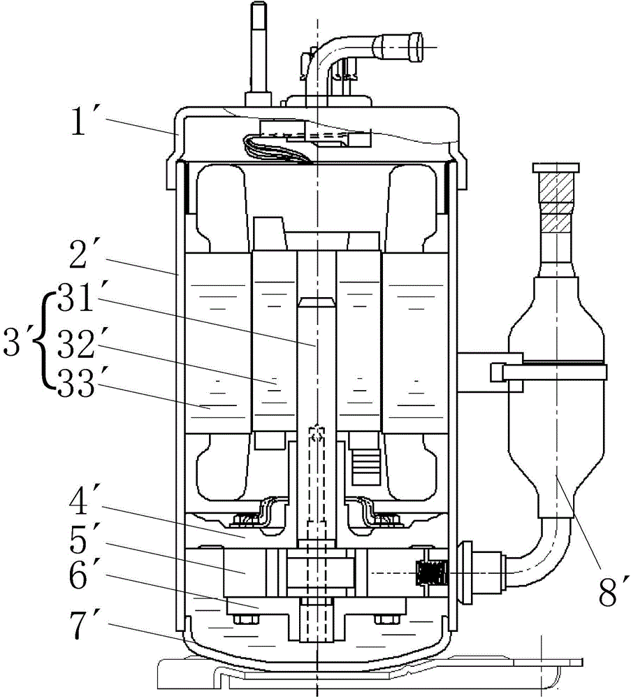
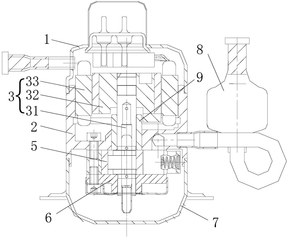
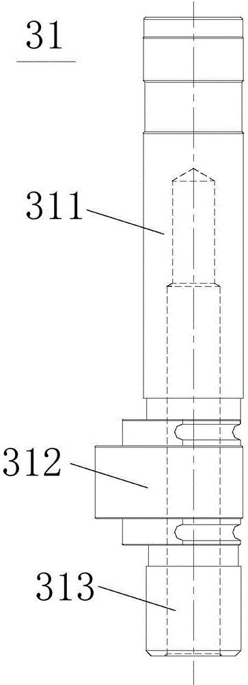
[0080] Such as figure 2 and image 3 As shown, the micro-compressor of the present invention includes: a housing; the motor 3 is accommodated in the upper space in the housing; the cylinder 5 is accommodated in the lower space in the housing; the crankshaft 31 has a long axis portion 311 and an eccentric portion 312 and short axis portion 313 (such as image 3 As shown), the rotational force of the motor 3 is transmitted to the cylinder 5 to compress the refrigerant; the first bearing assembly and the second bearing assembly together define the compression space with the cylinder 5 and support the crankshaft 31, wherein the first bearing assembly includes at least Upper bearing (ie main bearing) 2 and bushing 9, upper bearing 2 is located between motor 3 and cylinder 5. The second bearing assembly includes at least a lower bearing (ie a secondary bearing) 6 .

[0081] Such as Figure 4 As shown, the upper bearing 2 has a disc portion 21 with a through hole 24, an inner ed...

no. 2 example

[0093] Such as Figure 7 As shown, in a modification example, the upper bearing 2a may also be a disc portion 21a with a through hole 24a and an outer edge portion extending up and down from the outer edge of the disc portion 21a, and the middle cross section of the upper bearing 2a as a whole is H shape. The height of the bushing 9a matched with the upper bearing 2a is greater than or equal to the thickness of the disc portion 21a. and Figure 4 and Figure 5 The first embodiment shown differs in that, as Figure 7 The inner edge portion 25 of the upper bearing 2 has been canceled in the upper bearing 2a (see Figure 5 ). After canceling the inner edge portion 25, the main part of the upper bearing 2a becomes a simple planar structure (disc portion 21a), and the processing becomes easier, and the inner circular surface of the through hole 24a of the upper bearing 2a is no longer used for matching , the machining accuracy is also reduced, therefore, the overall machining...

no. 3 example

[0095] Such as Figure 8 As shown, in a variation example, with Figure 4 and Figure 5 Unlike the first embodiment shown, Figure 8 The inner edge portion 25b of the upper bearing 2b is shown as an inner cylindrical shape protruding from the disc portion 21b. The inner circular surface of the through hole 24b is jointly constituted by the inner peripheral surface of the disc portion 21b and the inner peripheral surface of the inner edge portion 25b. Moreover, the height of the bushing 9b is equal to the sum of the thicknesses of the disk portion 21b and the inner edge portion 25b, so that the inner circular surface of the through hole 24b (the inner peripheral surface of the disk portion 21b and the inner peripheral surface of the inner edge portion 25b) is more compact. Well support the bushing 9b. Similarly, the inner circular surface of the through hole 24b of the upper bearing 2b is no longer used for matching, therefore, the overall processing difficulty of the upper...


PUM


Abstract

The invention provides a compressor. The compressor comprises a shell; a motor and a cylinder, which are accommodated in the shell; a crankshaft, which comprises a long shaft part, an eccentric part and a short shaft part and is used for transmitting the rotary force of the motor to the cylinder to compress a refrigerant; and a first bearing assembly and a second bearing assembly, which define a compression space together with the cylinder and are used for supporting the crankshaft, wherein the first bearing assembly comprises a main bearing and a bush, the main bearing is located between the motor and the cylinder and provided with a through hole, and the bush is arranged in the through hole in a matching way and provided with an inner hole for supporting the crankshaft, which enables the bush to sleeve the long shaft part of the crankshaft. The compressor provided by the invention can meet requirements on wearing of a friction pair composed of the main bearing and the crankshaft and requirements on welding of the bearing and upper and lower shell covers, and reduces processing difficulty of conventional bearings at the same time.

Description

technical field [0001] The invention relates to a compressor, in particular to a fully enclosed rolling rotor compressor. Background technique [0002] In general, a hermetic compressor includes a motor for generating a driving force in an inner space of a hermetically sealed case, and a compression part coupled to the motor for compressing refrigerant. Hermetic compressors can be classified into reciprocating compressors, scroll compressors, and rolling rotor compressors according to different refrigerant compression mechanisms. Reciprocating compressors, scroll compressors, and rolling rotor compressors all utilize the rotational force of an electric motor. [0003] The motor of the existing hermetic compressor utilizing rotational force has a crankshaft, and the rotational force of the motor is transmitted to the compression part through the crankshaft. figure 1 Shown is a structural schematic diagram of a rolling rotor compressor in the prior art. As shown in the figu...

Claims


Application Information

Patent Timeline
Patent Type & Authority Applications(China)
IPC IPC(8): F04C29/00
Inventor 沈建芳张常春刘杨
Owner SHANGHAI HITACHI ELECTRICAL APPLIANCES CO LTD
Why Eureka
Try Eureka