Thrust bar lightening method and lightened thrust bar

A thrust rod, lightweight technology, applied in the direction of the cantilever mounted on the pivot, suspension, transportation and packaging, etc., can solve the problem of light weight impact, to achieve the effect of reducing weight, reducing weight and increasing extrusion force

Active Publication Date: 2017-05-10
BOGE RUBBER&PLASTICS ZHUZHOU CO LTD
View PDF6 Cites 19 Cited by
  • Summary
  • Abstract
  • Description
  • Claims
  • Application Information

AI Technical Summary

Problems solved by technology

[0009] It can be seen from the above-mentioned patent documents that the thrust rod belongs to the first combination scheme. The rod body of the thrust rod is formed by riveting or welding between the ball head and the pipe body. Sufficient structure to provide the interface or loss required for riveting or welding, so it also has a certain impact on lightweight

Method used


Image

  • Thrust bar lightening method and lightened thrust bar
  • Thrust bar lightening method and lightened thrust bar
  • Thrust bar lightening method and lightened thrust bar

Examples


Embodiment 1

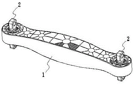
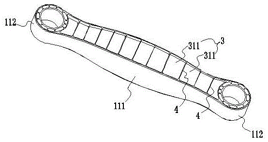
[0041] Embodiment 1: as Figure 1 to Figure 4 As shown, a thrust rod lightening method, the thrust rod lightening method is that the rod body 1 and the mandrel 211 of the elastic ball hinge 2 are both made of polymer materials and molded by injection molding at one time, and the opposite two sides of the rod body 111 are molded at one time. They are all arranged as side surfaces with discontinuous grooves 1, which include a plurality of sub-grooves 3 distributed sequentially along the length direction of the rod body 111 (that is, two or more than two sub-grooves). Groove 1), on the groove bottom surface of each sub-groove-3, a plurality of convex ribs 4 (that is, two or more than two ribs) are arranged, so that each sub-groove-3 is covered by multiple The rib 4 is divided into a plurality of small grooves 311 (that is, two or more small grooves). In this embodiment, the rod body 111 is set in a rectangular shape, and the two ball heads 5 are set in a hollow Cylindrical.

[...

Embodiment 2

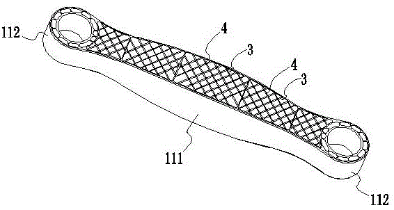
[0054] Embodiment 2: as Figure 9 As shown, compared with Embodiment 1, the difference is that: the plurality of ribs 4 arranged on the bottom surface of the groove of each sub-groove-3 are parallel to each other, and the plurality of ribs 4 are all parallel to the rod body. The main body 111 is arranged in the lengthwise direction, so that the arrangement can form a symmetrical structure, so that the stress conditions of all parts of the rod body are basically the same, and the product will not be damaged in advance due to excessive stress at a local position.

Embodiment 3

[0055] Embodiment 3: as Figure 10 As shown, compared with Embodiment 1, the difference is that: the plurality of ribs 4 arranged on the bottom surface of the groove of each sub-groove-3 are parallel to each other, and the plurality of ribs 4 are all along the vertical direction of the rod body. The length direction of the body is set, which can increase the bending resistance of the product, and has achieved the purpose of reducing the cross-sectional area and reducing the weight of the product.


PUM


Abstract

The invention discloses a thrust bar lightening method and a lightened thrust bar. According to the thrust bar lightening method, a bar body and a mandrel of an elastic spherical hinge are made of a high polymer material and formed at a time through injection molds, the two opposite side faces of the bar body are set to be the side faces with first intermittent grooves, each first intermittent groove comprises multiple first sub grooves sequentially distributed in the length direction of the bar body, multiple protruding ribs are arranged on the bottom face of each first sub groove, and therefore each first sub groove is divided into multiple small grooves through the multiple protruding ribs. On the premise that the use requirements of the thrust bar are met, the weight of the thrust bar can be reduced as much as possible, and the lightening requirement of the thrust bar is met.

Description

technical field [0001] The invention relates to a method for reducing the weight of a motor vehicle component and a lightweight locomotive component manufactured by the method, in particular to a method for reducing the weight of a thrust rod and the lightweight thrust rod. Background technique [0002] With the development of society, the exploitation and consumption of various energy sources are increasing, and pollution has become a focus of global attention. Therefore, in the face of the increasing number of motor vehicles, the requirements for exhaust emissions are also getting higher and higher. To reduce exhaust pollution as much as possible, we must pay attention to the NVH of automobiles. Therefore, major OEMs have begun to invest a lot of manpower, material and financial resources to meet the national requirements in the shortest possible time and quickly occupy the market. The light weight of the rod has become the easiest to realize and the most important problem...

Claims


Application Information

Patent Timeline
Patent Type & Authority Applications(China)
IPC IPC(8): B60G7/00B29C45/00
CPCB29C45/00B60G7/00B60G7/001B60G2206/11
Inventor 谢端康夏勇陈军郭春杰刘建林彭立华邹波路英竹
Owner BOGE RUBBER&PLASTICS ZHUZHOU CO LTD
Why Eureka
Try Eureka