Rotary liquid whistle cavitation generator

A generator and rotor technology, which is applied in the field of rotating liquid whistle cavitation generators, can solve problems affecting cavitation efficiency, large liquid axial back-mixing, etc., to achieve improved cavitation intensity, small axial back-mixing, and improved the effect of the effect

Pending Publication Date: 2017-05-10
ZHEJIANG UNIV OF TECH +1
View PDF7 Cites 4 Cited by
  • Summary
  • Abstract
  • Description
  • Claims
  • Application Information

AI Technical Summary

Problems solved by technology

The device has a large liquid flux, but the device has a large liquid axial back-mixing, which affects the further improvement of cavitation efficiency

Method used


Image

  • Rotary liquid whistle cavitation generator
  • Rotary liquid whistle cavitation generator
  • Rotary liquid whistle cavitation generator

Examples


Embodiment Construction

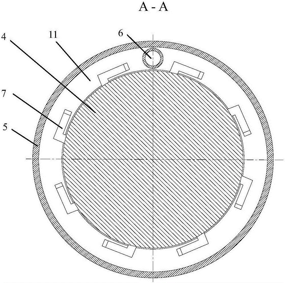
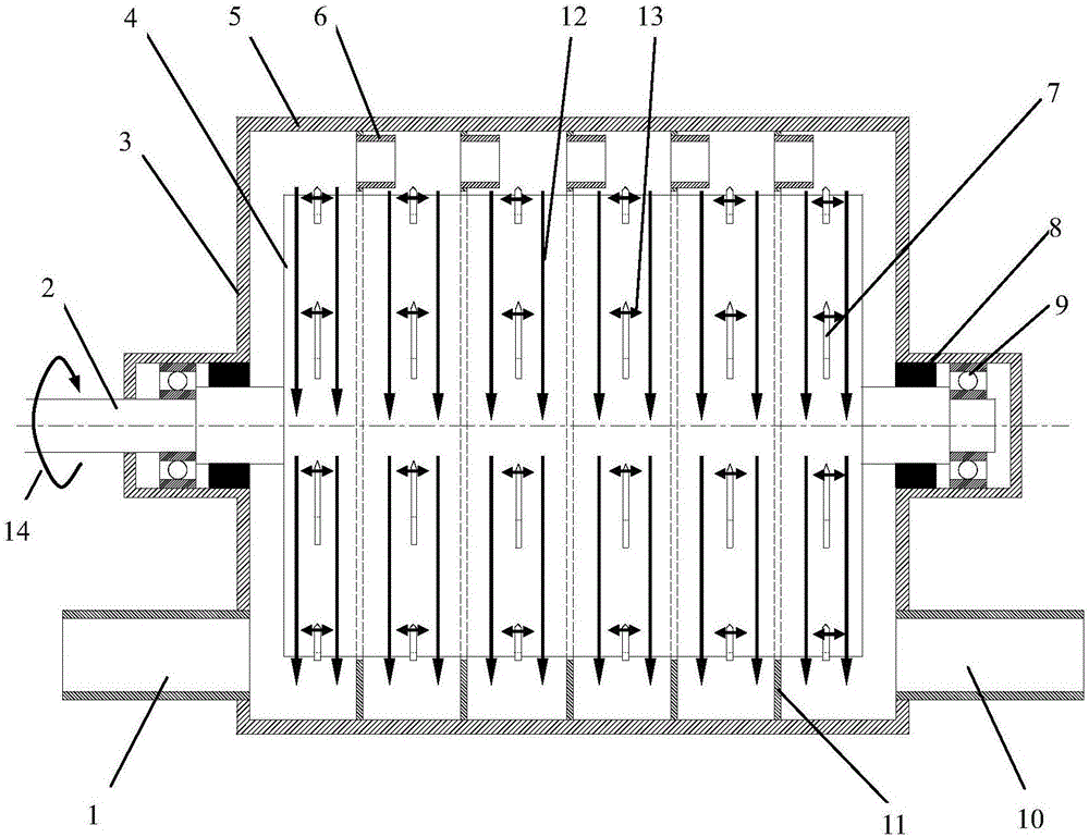
[0048] The rotating liquid whistle cavitation generator includes a coaxial rotor 4, a casing 5 and a rotating shaft 2, the rotor 4 is fixedly sleeved on the rotating shaft 2, and the casing 5 is placed outside the rotor 4. The two sides of the casing 5 The end is provided with a bearing 2, the rotating shaft 2 is rotatably connected to the housing 5 through the bearing, and one end of the rotating shaft 2 passes through the housing 5 and is connected to a power device for output torque;

[0049] A sealing device 8 is provided between the two ends of the housing 5 and the rotating shaft, there is a gap between the inner wall surface of the housing 5 and the outer wall surface of the rotor 4, and the inner wall surface of the housing 5 , the outer wall surface of the rotor 4 and the sealing device 8 form a sealed inner cavity;

[0050] One end of the housing 5 is provided with a liquid inlet 1, and the other end of the housing 5 is provided with a liquid outlet 10, and both the ...


PUM


Abstract

The invention discloses a rotary liquid whistle cavitation generator which comprises coaxially arranged rotors, housing and rotating shaft, wherein a sealing device is arranged between each end of the housing and the rotating shaft; a gap is formed between an inner wall surface of the housing and an outer wall surface of each rotor; a sealed inner cavity is surrounded by the inner wall surface of the housing, the outer wall surfaces of the rotors and the sealing devices; a liquid inlet is formed in one end of the housing; a liquid outlet is formed in the other end of the housing; the liquid inlet and the liquid outlet are communicated with the inner cavity; a plurality of annular partition plates are axially arranged in the housing at intervals; outer peripheries of the annular partition plates are fixed onto the inner wall surface of the housing; the rotor is rotationally penetrated in central through holes of the annular partition plates; the inner cavity is divided into a plurality of sealed sub-cavities by the annular partition plates; a short pipe is arranged on the partition plate between the adjacent sub-cavities; the two adjacent sub-cavities are communicated by the short pipe; a plurality of spring pieces are uniformly distributed on the rotor located in each sub-cavity; the spring pieces are fixed on the outer wall surfaces of the rotors in the radial direction of the rotors.

Description

technical field [0001] The invention relates to a rotating liquid whistle cavitation generator. Background technique [0002] Cavitation is the process of formation, development and collapse of vapor or gas voids (cavities) inside a liquid, and is a very complex fluid dynamics phenomenon. When the cavitation moves and collapses in the liquid, it will generate instantaneous high temperature and high pressure, accompanied by strong shock waves and high-speed jets. According to different methods of generating cavitation, cavitation can be divided into four categories: ultrasonic cavitation, hydraulic cavitation, optical cavitation and particle cavitation. [0003] The cavitation used in the chemical industry is mainly ultrasonic cavitation and hydraulic cavitation. Ultrasonic cavitation refers to a series of dynamic processes such as vibration, extrusion, shrinkage, fracture, growth and collapse of tiny bubbles (gas nuclei) in a liquid under the alternating action of positive...

Claims


Application Information

Patent Timeline
Patent Type & Authority Applications(China)
IPC IPC(8): C02F1/34
CPCC02F1/34
Inventor 计建炳李育敏张斌朱星剑赖水红徐之超其他发明人请求不公开姓名
Owner ZHEJIANG UNIV OF TECH
Why Eureka
Try Eureka