Cloth feeding mechanism of sewing machine

A cloth feeding mechanism and sewing machine technology, applied in the direction of cloth feeding mechanism, sewing machine components, sewing machine control devices, etc., can solve the problems of narrow application range, low cloth feeding efficiency, and inability to satisfy knitting and weaving at the same time, and reach the applicable scope Wide, easy-to-operate effect

Active Publication Date: 2017-05-10
JACK SEWING MASCH CO LTD
View PDF6 Cites 26 Cited by
  • Summary
  • Abstract
  • Description
  • Claims
  • Application Information

AI Technical Summary

Problems solved by technology

In view of the improvement of the current sewing process requirements, a single elliptical inclined trajectory can no longer fully meet the sewing of different types of fabrics in the market
In this kind of cloth feeding mechanism, it is easy to have sewing defects such as misalignment of upper and lower layers of cloth, the same machine cannot satisfy knitting and weaving at the same time, the cloth does not wrinkle, or the cloth feeding efficiency is low.
Therefore, this kind of cloth feeding mechanism cannot adjust the inclination angle of the cloth feeding track during use, and its applicable range is narrow

Method used


Image

  • Cloth feeding mechanism of sewing machine
  • Cloth feeding mechanism of sewing machine
  • Cloth feeding mechanism of sewing machine

Examples


Embodiment Construction

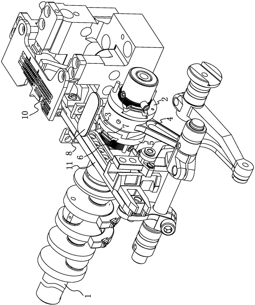
[0024] Such as figure 1 As shown, the sewing machine feed mechanism includes a main shaft 1 arranged in the sewing machine frame.

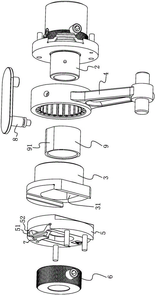
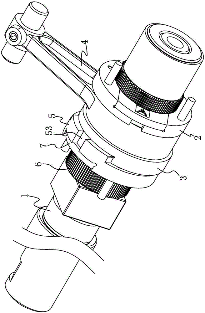
[0025] Such as figure 1 and figure 2 As shown, in this embodiment, a ratchet 6, a base 5, an eccentric wheel 3, a cloth feeding connecting rod 4, and a needle distance eccentric wheel 2 are sequentially set on the main shaft 1 from left to right, and the outside of the needle distance eccentric wheel 2 The cover is provided with a limit sleeve 9, and the limit sleeve 9 is located in the eccentric wheel one 3. Wherein, the ratchet 6, the base 5, the eccentric wheel 3, the needle distance eccentric wheel 2 and the limit sleeve 9 are all in the shape of a ring, and the end of the cloth feeding connecting rod 4 which is sleeved on the eccentric wheel 3 is also in the shape of a ring . One end of the eccentric wheel one 3 is slidably arranged on the base 5 along the radial direction of the main shaft.

[0026] Specifically, such as Figure 5 As ...


PUM


Abstract

The invention discloses a cloth feeding mechanism of a sewing machine and belongs to the technical field of sewing machines. By means of the cloth feeding mechanism, the problem that an original cloth feeding mechanism of the sewing machine is narrow in application range is solved. The cloth feeding mechanism of the sewing machine comprises a main shaft which is sleeved with a stitch length eccentric wheel, a first eccentric wheel is arranged on the outer side of the stitch length eccentric wheel, the first eccentric wheel is internally provided with a first sliding groove, the stitch length eccentric wheel can slide in the first eccentric wheel, the sliding direction in which the stitch length eccentric wheel slides in the first eccentric wheel is eccentrically arranged relative to the first eccentric wheel, and a cloth feeding connecting rod is arranged outside the stitch length eccentric wheel in a sleeving mode; a base is arranged on the main shaft in a sleeving mode, and the first eccentric wheel is arranged on the base in a sliding mode in the radial direction of the main shaft; a clutch mechanism is arranged between the base and the main shaft. Due to the arrangement of the clutch mechanism between the base and the main shaft, the inclination angle of the elliptical motion track of a cloth feeding dog can be conveniently adjusted by means of the cloth feeding mechanism.

Description

technical field [0001] The invention belongs to the technical field of sewing machines, and relates to a cloth feeding mechanism of a sewing machine. Background technique [0002] Chinese utility model patent (authorized announcement number: CN204097699U, authorized announcement date: 20160114) discloses a cloth feeding mechanism for an overlock sewing machine. In its background technology, it is mentioned that the existing cloth feeding mechanism of overlock sewing machine includes main shaft, cloth feeding eccentric wheel, small eccentric wheel, eccentric wheel, first needle roller bearing, cloth feeding connecting rod, needle pitch eccentric wheel, fourth axis Pins, screws, sliders, outer ring gears, springs, feed cranks, feed shafts. Wherein the eccentric wheel, the first needle roller bearing, the cloth feeding connecting rod, the needle distance eccentric wheel, the fourth shaft pin, the screw, and the spring are assembled into a whole (part A) earlier, and a small sp...

Claims


Application Information

Patent Timeline
Patent Type & Authority Applications(China)
IPC IPC(8): D05B27/02D05B69/02
CPCD05B27/02D05B69/02
Inventor 芈韶雷宋国庆吴平赵林蔚
Owner JACK SEWING MASCH CO LTD
Why Eureka
Try Eureka