An Axial Moving Multi-mode Hydraulic Variable Valve Drive System

A drive system, axial movement technology, applied in the direction of engine components, machines/engines, non-mechanically actuated valves, etc., to achieve good application prospects, high reliability, and compact mechanism

Inactive Publication Date: 2018-12-25
DALIAN UNIV OF TECH
View PDF6 Cites 0 Cited by
  • Summary
  • Abstract
  • Description
  • Claims
  • Application Information

AI Technical Summary

Problems solved by technology

At present, there is no variable valve drive system that can meet the above requirements at the same time, so the development of a multi-mode variable valve drive system is imminent

Method used


Image

  • An Axial Moving Multi-mode Hydraulic Variable Valve Drive System
  • An Axial Moving Multi-mode Hydraulic Variable Valve Drive System
  • An Axial Moving Multi-mode Hydraulic Variable Valve Drive System

Examples


Embodiment Construction

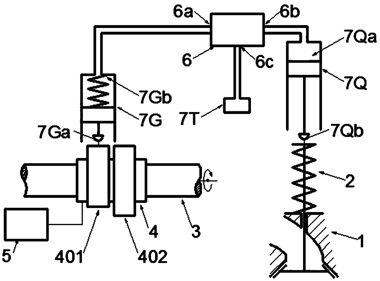
[0047] The invention relates to an axially movable multi-mode hydraulic variable valve drive system. It includes valve driving mechanism 2, camshaft 3, camshaft sleeve 4, axial movement mechanism 5, valve control mechanism 6, plunger type oil supply device 7G, piston type driver 7Q and oil reservoir 7T. figure 1 It is a schematic diagram of an axially moving multi-mode hydraulic variable valve drive system with a single camshaft bushing and a single set of cams, a double cam drive, a single valve operation and a single adjustment. A first cam 401 and a second cam 402 are arranged on the camshaft sleeve 4 . The first cam 401 adopts a single-lobed cam blade or a double-lobed cam blade, the second cam 402 adopts a single-lobed cam blade or a double-lobed cam blade, and the double-lobed cam blades adopt camshafts with the same profile and a phase difference of 180° Two protrusions at the corners. The plunger type oiler 7G has a plunger input port 7Ga and an oil supply chamber 7G...


PUM


Abstract

An axially movable multi-mode hydraulic variable valve driving system belongs to the field of engine valve driving. It mainly includes camshaft, camshaft sleeve, axial movement mechanism, valve control mechanism, plunger type oil supply device, piston type driver and oil reservoir, etc. At least a first cam and a second cam are arranged on the camshaft sleeve. Through the use of the axial movement mechanism, the conversion between the two-stroke driving mode, the four-stroke driving mode, the two-stroke braking mode, the four-stroke braking mode and other modes of the engine is realized; further through the use of the valve control mechanism, the final realization It ensures the best ventilation of the engine under different working conditions, and achieves the purpose of comprehensively improving engine power, fuel economy, emission and braking safety. The present invention is proposed for practical application, has high reliability and compact mechanism, and reduces the requirements of the system on each mechanism. Each mechanism adopts a relatively mature technology, and the system has a high practical potential in a short period of time and has a good application prospect.

Description

technical field [0001] The invention relates to an axially movable multi-mode hydraulic variable valve drive system, which belongs to the field of engine valve drive. Background technique [0002] With the increasingly serious energy and environmental issues, and people's focus on driving and safety of vehicles, future engines need to comprehensively consider power, economy, emissions and safety on the premise of meeting emission standards. This requires optimizing engine performance over the full range of driving and braking conditions. At present, technologies such as variable valve, variable stroke number, cylinder deactivation, auxiliary braking, new combustion mode, variable compression ratio, variable EGR and other technologies that have attracted much attention only affect the performance of the engine in a small range of operating conditions. Make improvements. For example, the existing variable valve technology is only applied to the driving condition of the fixed...

Claims


Application Information

Patent Timeline
Patent Type & Authority Patents(China)
IPC IPC(8): F01L9/02F01L9/12
CPCF01L9/12
Inventor 隆武强崔靖晨田华田江平王阳刘威杨添淏
Owner DALIAN UNIV OF TECH
Why Eureka
Try Eureka