Oil discharge valve of engine sump and control circuit of oil discharge valve

A technology for engine oil and valves, applied in the direction of adding/discharging lubricants and lubricating parts, etc., can solve the problems of heavy workload, increased use cost and workload, waste of gaskets, etc., and achieve simple and convenient installation and easy oil discharge Faster and safer effects

Active Publication Date: 2017-05-10
上海轩维汽配制造有限公司
View PDF4 Cites 1 Cited by
  • Summary
  • Abstract
  • Description
  • Claims
  • Application Information

AI Technical Summary

Problems solved by technology

[0003] 1. The traditional way of bolts and gaskets has the following defects: every time the vehicle needs to change the oil, it needs to use special equipment to lift the vehicle first, and some models also need to dismantle the bottom guard, and then unscrew the bolts with a wrench to replace the engine. The oil in the oil pan is released, and the gasket needs to be replaced after the oil is drained, and finally the bolts are tightened with a torque of 30-40N. The waste of gaskets and frequent oil changes are likely to cause the bolts of the oil pan to slip. Over time, the entire oil pan needs to be replaced, or the threads must be reprocessed
This method requires external special tooling, which increases the use cost and workload. It also needs to be equipped with a waterproof and dustproof rubber cap. When the engine is running, the heat will be transferred to the rubber cap, which will accelerate the aging of the rubber cap and affect its protective effect.

Method used


Image

  • Oil discharge valve of engine sump and control circuit of oil discharge valve
  • Oil discharge valve of engine sump and control circuit of oil discharge valve
  • Oil discharge valve of engine sump and control circuit of oil discharge valve

Examples


Embodiment Construction

[0024] The present invention is described in detail below in conjunction with embodiment example, present embodiment is carried out under the premise of technical solution of the present invention, has provided detailed embodiment and specific operation process, but protection scope of the present invention is not limited to following implementation example.

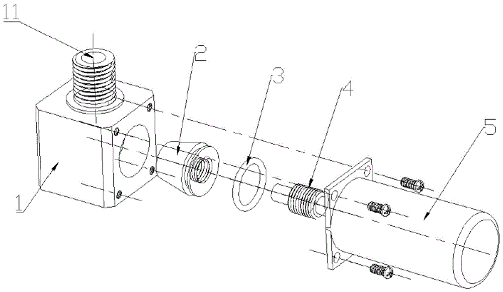
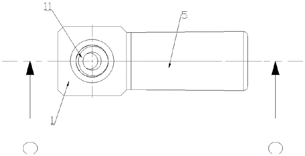
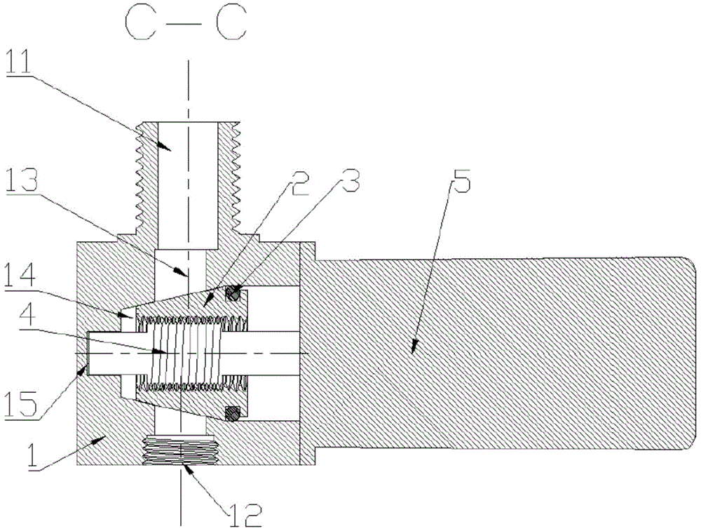
[0025] like figure 1 As shown, the oil drain valve of the engine oil pan includes a valve body 1, a valve core 2, a screw rod 4 and a motor 5 with a reducer. End face area, where:

[0026] An oil inlet 11 is arranged on the outer side of the top of the valve body 1, and an oil passage 13 is vertically arranged on the upper and lower surfaces of the valve body 1 in the valve body 1, and the oil passage 13 is not coaxial with the oil inlet 11. 13 outlet is provided with an oil discharge port 12; perpendicular to the axial direction of the oil passage 13 is provided with a spool cavity 14, the spool 2 is arranged in the s...


PUM


Abstract

The invention provides an oil discharge valve of an engine sump and a control circuit of the oil discharge valve, and belongs to the technical field of valves and electric control circuits thereof. By the oil discharge valve of the engine sump, oil can be discharged from the engine sump conveniently and controllably. An oil inlet is formed in the outer side of the top of a valve body; an oil channel is formed in the valve body; an oil discharge opening is formed in an outlet of the oil channel; a valve element chamber is formed in a position perpendicular to the axis direction of the oil channel; a valve element is arranged in the valve element cavity; a mounting blind hole is formed in one side, which is close to the end surface of the front of the valve element, of the side wall of the valve body; a motor with a speed reducer is arranged outside the valve body; a lead screw is fixedly arranged on an output shaft of the motor with the speed reducer; an end of the output shaft of the motor with the speed reducer penetrates through the valve element chamber and is inserted in the mounting blind hole; the lead screw is in threaded connection with an inner threaded hole formed in the valve element; and the lead screw drives the valve element to horizontally move in the valve body in a reciprocating manner. The control circuit controls the motor to drive the valve element to move in the valve body, so that oil can be discharged from the engine sump conveniently, quickly and controllably.

Description

technical field [0001] The invention belongs to the technical field of valves and electric control circuits thereof, in particular to an oil drain valve of an engine oil pan and a control circuit thereof. Background technique [0002] After the vehicle runs for a certain mileage, the engine oil needs to be drained and replaced. There are two main ways to drain the engine oil at present: [0003] 1. The traditional way of bolts and gaskets has the following defects: every time the vehicle needs to change the oil, it needs to use special equipment to lift the vehicle first, and some models also need to dismantle the bottom guard, and then unscrew the bolts with a wrench to replace the engine. The oil in the oil pan is released, and the gasket needs to be replaced after the oil is drained, and finally the bolts are tightened with a torque of 30-40N. The waste of gaskets and frequent oil changes are likely to cause the bolts of the oil pan to slip. Over time, the entire oil pan...

Claims


Application Information

Patent Timeline
Patent Type & Authority Applications(China)
IPC IPC(8): F01M11/04
CPCF01M11/0408
Inventor 沈钟德
Owner 上海轩维汽配制造有限公司
Why Eureka
Try Eureka