
A Brake with Rapid Adjustment of Gap

A brake, rapid technology, applied in the direction of slack adjuster, hoisting device, etc., can solve the problems of low adjustment efficiency, high processing and manufacturing costs, etc., and achieve the effects of improving production efficiency, facilitating construction site maintenance, and guiding accurately and effectively

Active Publication Date: 2019-07-23
浙江西子富沃德电机有限公司
View PDF4 Cites 0 Cited by
  • Summary
  • Abstract
  • Description
  • Claims
  • Application Information

AI Technical Summary

Problems solved by technology

[0005] (2) The brake gap adjustment is realized by means of plugs. This type of product reduces the number of guide bolts (the guide pin is used between the electromagnet and the armature for guidance), and the product has higher requirements on the accuracy of the parts (the flatness of the end surface of the machine base, the installation position of the bearing and the plug thickness, etc.), through precision control to ensure the adjustment of the gap, this type of product has high requirements for the processing and manufacturing precision of parts, the processing and manufacturing cost is relatively high, and the adjustment efficiency is low

Method used


Image

  • A Brake with Rapid Adjustment of Gap
  • A Brake with Rapid Adjustment of Gap
  • A Brake with Rapid Adjustment of Gap

Examples


Embodiment Construction

[0036] Below in conjunction with the accompanying drawings, the brake for quick gap adjustment of the present invention will be described in detail. The marks and embodiments shown in the accompanying drawings should not be regarded as limitations to the technology of the present invention, any modification and increase on the basis of the present invention are considered to be within the protection scope of the present invention, and the structural form is not limited to the illustrated structural examples .

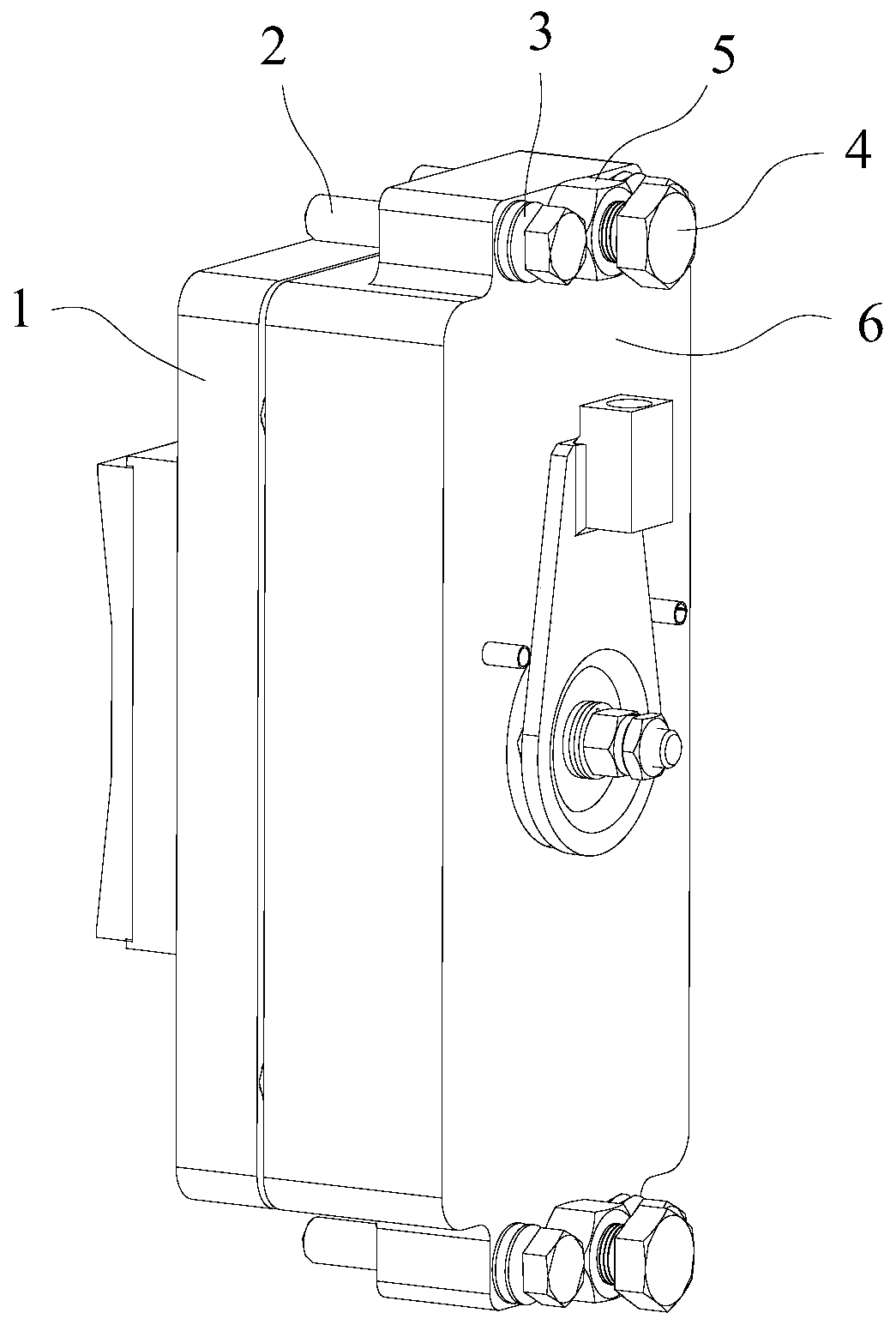
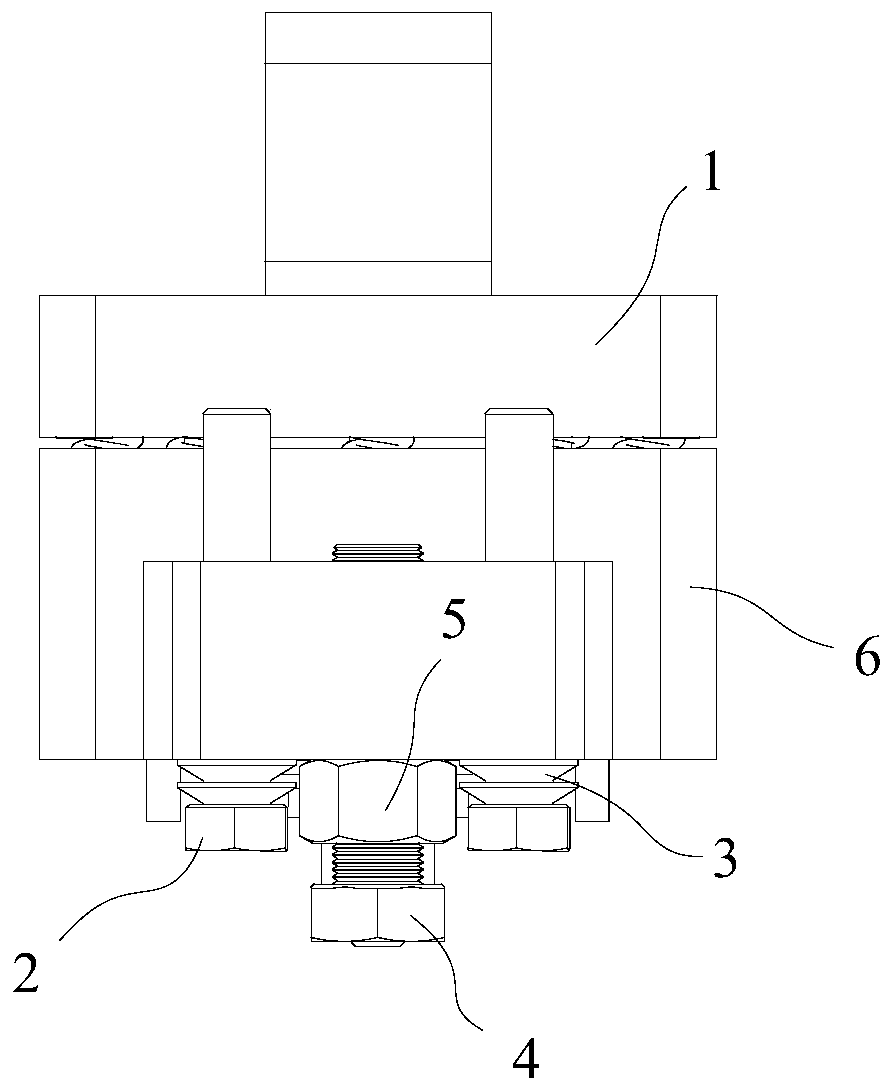
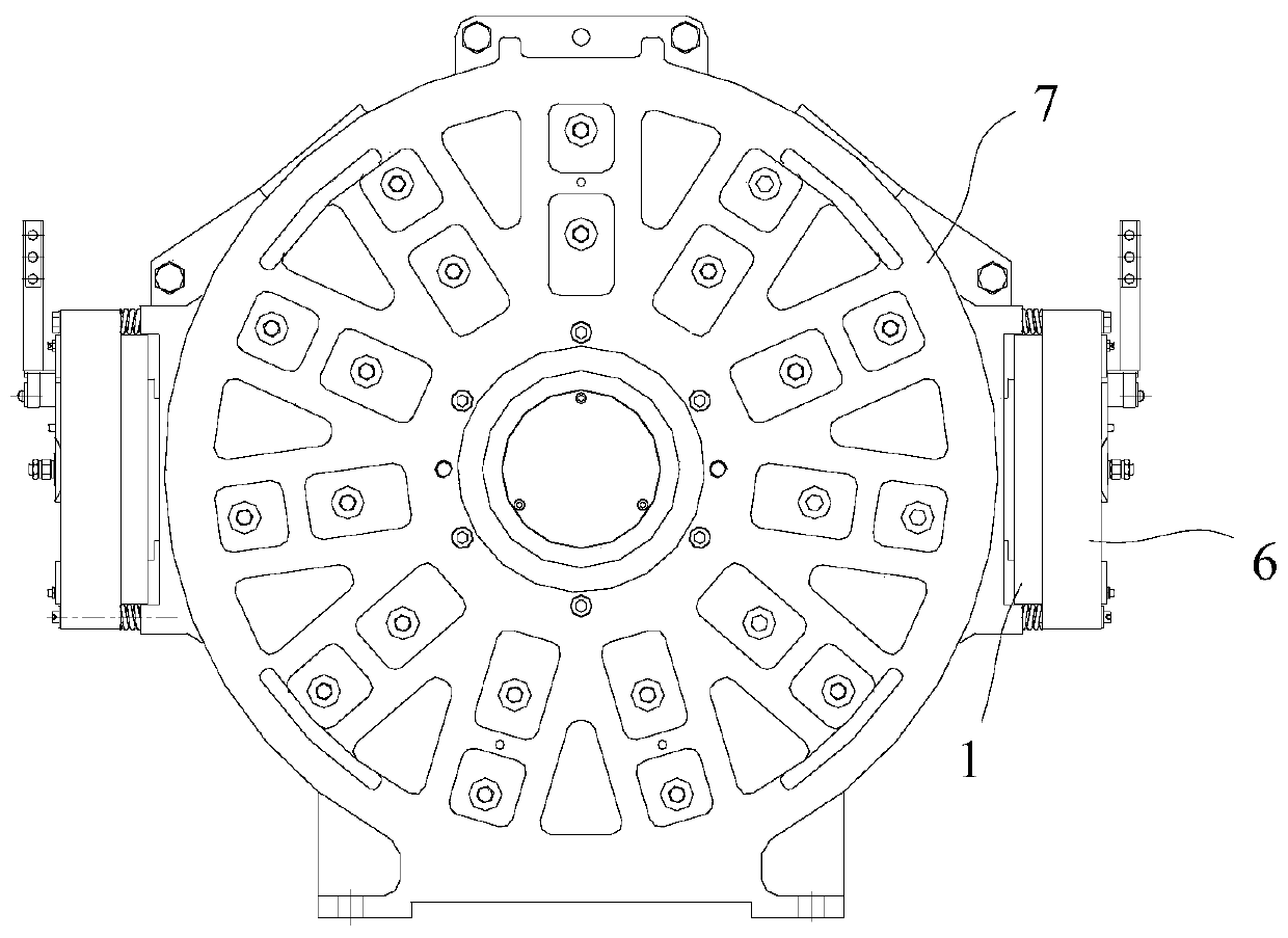
[0037] Such as figure 1 , figure 2 As shown, a brake with fast clearance adjustment includes an electromagnet 6 and an armature 1 that cooperate with each other. The electromagnet 6 is provided with a fastener (ie, the first bolt 2 ) and an adjusting member (ie, the second bolt 4 ).

[0038] Such as figure 1 , figure 2 As shown, the fastener is the first bolt 2 that slides through the electromagnet 6. The head of the first bolt 2 is located on the side of the elec...


PUM


Abstract

The invention discloses a brake with a fast clearance adjustment function. The brake comprises an electromagnet and an armature matched with the electromagnet. In the use status, the armature faces a mounting face, and the electromagnet is provided with fasteners used for fixing the brake on the mounting face, and adjustment pieces abutting against the mounting face, wherein the fasteners apply mounting pretightening force on the electromagnet toward the armature side through elastic elements, and the adjustment pieces apply adjustment force to the electromagnet, and the adjustment force backs onto the armature side and enables the elastic elements to deform. The fasteners are first bolts which slidably penetrate through the electromagnet. The heads of the first bolts are located on the side, backing onto the armature, of the electromagnet, the elastic elements are pressed between the first bolts and the electromagnet in an abutting mode, and the rod portions of the first bolts extend out of the armature side and are used for being in threaded fit with the mounting face to generate the mounting pretightening force. By adoption of the brake with the fast clearance adjustment function, clearances of the brake can be fast adjusted, the production efficiency is improved, construction site maintenance is facilitated, the labor intensity for brake clearance adjustment is greatly relieved, and the product quality can be guaranteed.

Description

technical field [0001] The invention relates to the technical field of traction machine brakes, in particular to a brake with fast clearance adjustment. Background technique [0002] In view of the current elevator industry's requirements for the precise air gap and convenient adjustment method of the traction machine brake, it is an inevitable trend to change the structural form and convenient adjustment method of the electromagnetic brake for the traction machine. By changing the structure and adjustment method of the electromagnetic brake, the structure can be simplified, the labor intensity and assembly skill requirements of assembly can be reduced, and the site maintenance of the product can be facilitated, and the performance of the product can be improved. [0003] The electromagnetic brakes for traction machines currently on the market usually use the following two methods for clearance adjustment: [0004] (1) Clearance adjustment is realized through the principle ...

Claims


Application Information

Patent Timeline
Patent Type & Authority Patents(China)
IPC IPC(8): F16D65/38B66D5/00
CPCB66D5/00F16D65/38
Inventor 徐璐李峥游青平江徽
Owner 浙江西子富沃德电机有限公司
Learn More