Sintering device of LED bulb

A technology of LED bulbs and sintering devices, which is applied in lighting devices, semiconductor devices of light-emitting elements, light sources, etc., can solve the problems of lamp housing displacement, inaccurate calibration work, and affecting calibration quality, so as to achieve uniform gas volume and avoid distortion Effect

Active Publication Date: 2017-05-10
宁阳县鑫农农村发展有限公司
View PDF7 Cites 5 Cited by
  • Summary
  • Abstract
  • Description
  • Claims
  • Application Information

AI Technical Summary

Problems solved by technology

However, due to the limited observation degree of human eyes, when calibrating small light bulbs, the calibration work is inevitably not accurate enough, which affects the calibration quality
In addition, in the existing sintering equipment, the

Method used


Image

  • Sintering device of LED bulb
  • Sintering device of LED bulb
  • Sintering device of LED bulb

Examples


Embodiment Construction

[0025] The present invention will be described in further detail below by means of specific embodiments:

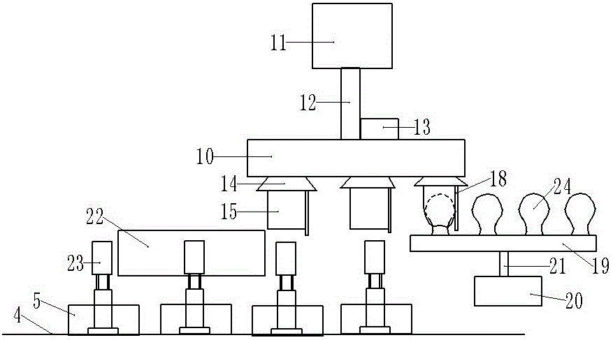
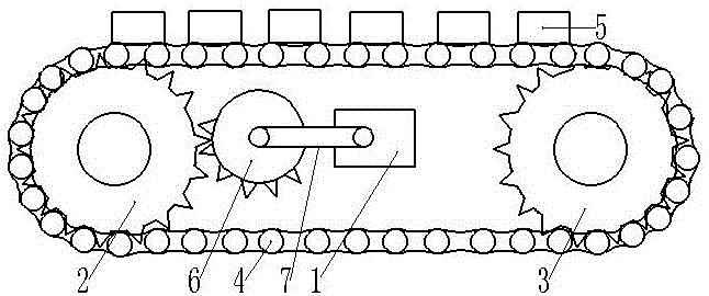
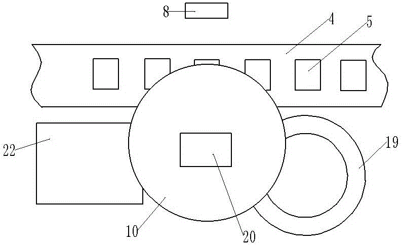
[0026] The reference signs in the drawings of the description include: the first reduction motor 1, the driving sprocket 2, the driven sprocket 3, the tooth chain 4, the station slot 5, the incomplete gear 6, the belt 7, the sintering nozzle 8, the second Valve 9, air box 10, second reduction motor 11, second rotating shaft 12, cylinder 13, cover plate 14, rotating air bag 15, air outlet pipe 16, first valve 17, air guide pipe 18, annular transfer groove 19, third Geared motor 20, third rotating shaft 21, bulb collection box 22, stem post 23, lamp housing 24.

[0027] The embodiment is basically as figure 1 , figure 2 and image 3 Shown: a sintering device for LED light bulbs, including a first geared motor 1 and a transmission mechanism, the first geared motor 1 is provided with a first rotating shaft, and the transmission mechanism includes a driving sprocket 2, a d...


PUM


Abstract

The invention relates to the field of LED bulb preparation technology, and discloses a sintering device of a LED bulb, comprising a first gear motor, a drive sprocket, a driven sprocket and an incomplete gear, wherein a chain transmission is arranged between the drive sprocket and the driven sprocket, and the incomplete gear is engaged with the drive sprocket, and connected to the first gear motor; a station slot is arranged on a tooth chain of which the outside is provided with a sintering nozzle; a gas tank is arranged above the tooth chain, and a second gear motor is arranged above the gas tank, and connected to the gas tank on which an air cylinder is arranged; the bottom of the gas tank is connected to cover plates of which the lower ends are all connected to rotary air bags of which the upper parts are provided with air outlet pipes distributed in the tangential direction of the outer circumference of the rotary air bags, and an annular conveying trough is arranged below the gas tank. The sintering device of the LED bulb disclosed by the invention is able to achieve automatic calibration of lamp housing and avoid distortion of the lamp housing.

Description

technical field [0001] The invention relates to the technical field of preparation of LED bulbs, in particular to a sintering device for LED bulbs. Background technique [0002] Traditional lighting is usually achieved by using incandescent lamps. Incandescent lamps use filaments to gather heat generated when current passes through the filaments, making the temperature of the filaments reach an incandescent state above 2000 degrees Celsius, so that the filaments emit light for lighting. In this process, incandescent lamps It needs to consume more heat to emit light, which is a waste of energy. In this context, people use diodes to make LED energy-saving lamps, which convert electrical energy into light directly through diodes to achieve lighting, reduce the energy consumed by bulb lighting, and achieve the purpose of energy saving and environmental protection. [0003] When producing LED light bulbs, it is necessary to sinter the base connected with the light-emitting diode...

Claims


Application Information

Patent Timeline
IPC IPC(8): F21K9/90C03C27/00F21Y115/10
CPCC03C27/00F21K9/90
Inventor 聂超
Owner 宁阳县鑫农农村发展有限公司
Why Eureka
Try Eureka