
Heat dissipation system of rail lamp

A technology for heat dissipation systems and lamps, which is applied to cooling/heating devices of lighting devices, lighting and heating equipment, semiconductor devices of light-emitting elements, etc. The effect of reducing heat dissipation volume and light weight

Pending Publication Date: 2017-05-10
SELF ELECTRONICS CO LTD
View PDF0 Cites 0 Cited by
  • Summary
  • Abstract
  • Description
  • Claims
  • Application Information

AI Technical Summary

Problems solved by technology

However, due to its heat dissipation, LED track lighting has been restricting its development in the direction of miniaturization and light weight, because most of the current lighting shells and radiators are designed separately, and the structural connections between the components cause poor heat dissipation. , and the shell becomes the main heat sink, which makes the overall heat dissipation capacity of the lamp limited and heavy and bulky, unable to meet the actual needs of users

Method used


Image

  • Heat dissipation system of rail lamp
  • Heat dissipation system of rail lamp
  • Heat dissipation system of rail lamp

Examples


Embodiment Construction

[0021] Specific embodiments of the present invention will be described in further detail below based on the accompanying drawings. It should be understood that the specific embodiments described here are only examples, and are not intended to limit the protection scope of the present invention.

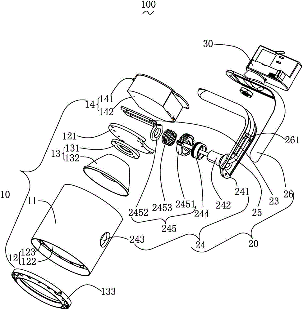
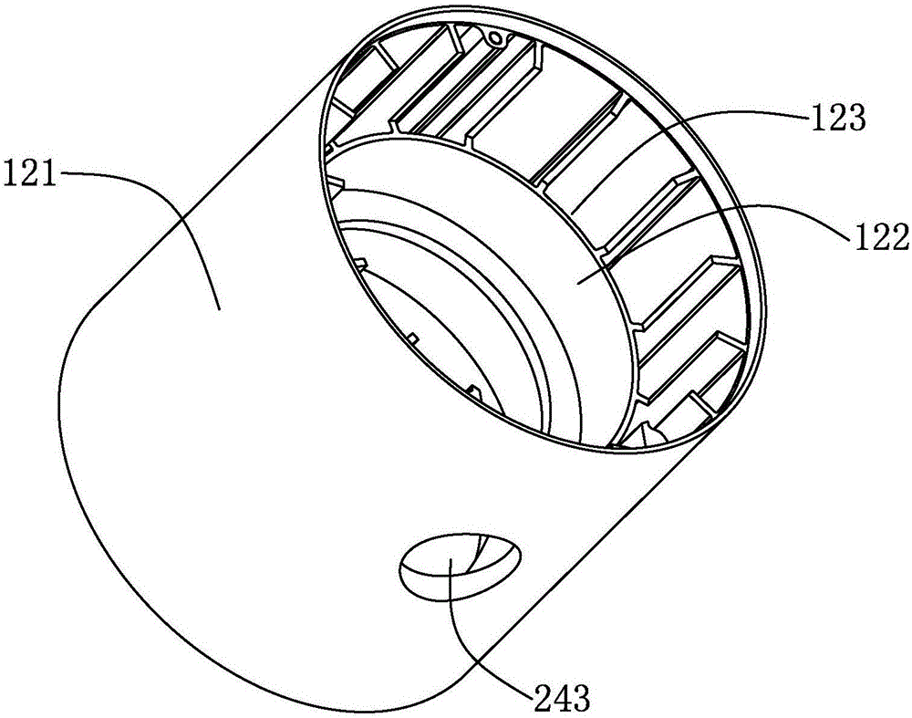
[0022] see figure 1 and figure 2 , which is a structural schematic diagram of a heat dissipation system 100 for a track light fixture provided by the present invention. The heat dissipation system 100 of the track lamp includes a lamp head 10 , a rotating handle 20 rotatably connected with the lamp head 10 , and a power plug 30 . It is conceivable that, in order for the track lamp to work normally, it should also have an electrified track, which is a well-known technology in the art and will not be described in detail here.

[0023] The lamp holder 10 includes a lamp tube 11, a lamp tube cooling subsystem 12 arranged in the lamp tube 11, a light source module 13 arranged in the la...


PUM


Abstract

A heat dissipation system of a rail lamp comprises a handle heat dissipation subsystem. The handle heat dissipation subsystem comprises a heat transfer base board, a cover board, a rotating mechanism and a heat pipe. A through hole used for the rotational arrangement of the heat pipe is formed between the cover board and the heat transfer board. The rotating mechanism comprises an inner handle, a rotating shaft, a shaft hole, a shaft sleeve and a jacking mechanism. The jacking mechanism moves along with the rotating shaft and comprises a jacking piece, a nut, and an elastic piece, wherein the rotating shaft is sleeved with the jacking piece, the nut is fixed at one end of the rotating shaft, and the elastic piece is arranged between the jacking piece and the nut in a clamping mode. According to the heat dissipation system of the rail lamp, under the effect of the rotating mechanism, the heat pipe can rotate along with the rotating handle, so that the rotating handle simultaneously has heat dissipation and rotating functions, and therefore, the heat dissipation volume of a lamp head is further reduced to achieve the purposes of miniaturization and the light weight of the whole lamp.

Description

technical field [0001] The invention relates to a lighting device, in particular to a cooling system for a track lamp. Background technique [0002] In general daily life, various lighting devices can be seen everywhere, for example, fluorescent lamps, street lamps, table lamps, art lamps and the like. Among the above-mentioned lighting devices, traditionally most of them use tungsten filament bulbs as light sources. In recent years, light-emitting diodes (LEDs) have been used as a source of light due to advances in technology. What's more, in addition to lighting equipment, for general traffic signs, billboards, car lights, etc., light-emitting diodes are also used as light-emitting light sources instead. As mentioned above, the advantage of using light-emitting diodes as a light source is that it saves power and has higher brightness, so it has gradually become popular in use. [0003] With the popularization of LED lamps, LED lamps are used in more and more occasions. ...

Claims


Application Information

Patent Timeline
IPC IPC(8): F21V29/51F21V29/70F21S8/00F21Y115/10
CPCF21S8/00F21V29/51F21V29/70
Inventor 陈兵
Owner SELF ELECTRONICS CO LTD
Features
  • Generate Ideas
  • Intellectual Property
  • Life Sciences
  • Materials
  • Tech Scout
  • Unparalleled Data Quality
  • Higher Quality Content
  • 60% Fewer Hallucinations
Learn More