Water inlet pipeline
A technology of water inlet pipeline and water inlet pipe, applied in the direction of pipeline layout, etc., can solve the problems of water layer disturbance and excessive water pressure, and achieve the effects of preventing cold and hot water disturbance, high work efficiency, and increasing scour flow.
- Summary
- Abstract
- Description
- Claims
- Application Information
AI Technical Summary
Problems solved by technology
Method used
Image
Examples
Embodiment 1
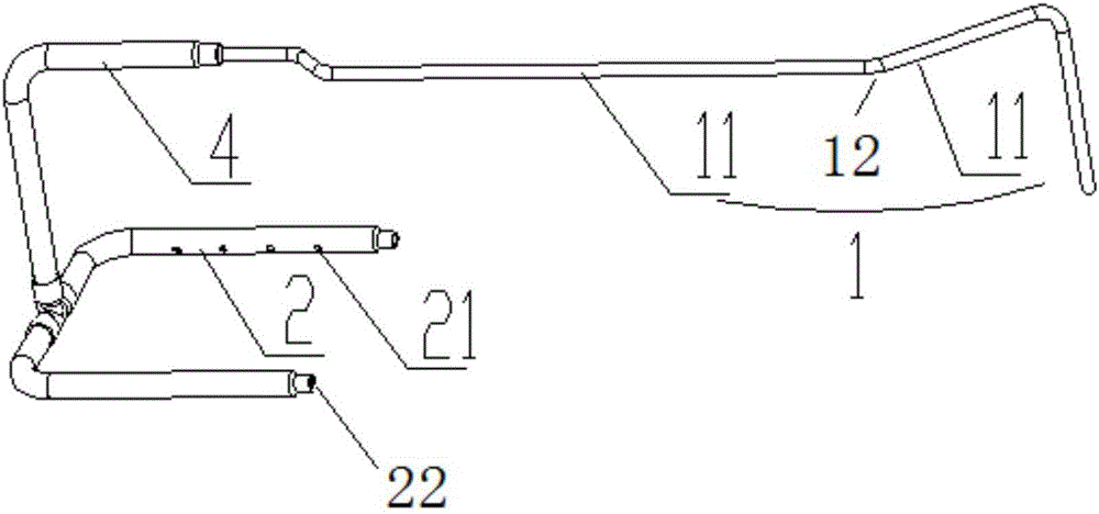
[0050] This embodiment provides a water inlet pipeline for precision air conditioners, such as figure 1 As shown, it includes: a water inlet pipe 1, connected to a water source and arranged in a water tank 3; The total cavity section is smaller than the total cavity section of the water outlet pipe 2 .
[0051] In this embodiment, there is one water inlet pipe 1, and one water outlet pipe. The inner cavity cross section of the water inlet pipe 1 is smaller than the inner cavity cross section of the water outlet pipe 2, and the water flows from the small area inner cavity of the water inlet pipe into the large area inner cavity of the water outlet pipe. , the water pressure decreases and the water flow decreases. At the same time, when water flows from the water inlet pipe 1 into the water outlet pipe 2 with a large inner cavity section, the water outlet pipe 2 plays the role of water storage, which can further slow down the flow velocity of the water. Therefore, after the wat...
Embodiment 2
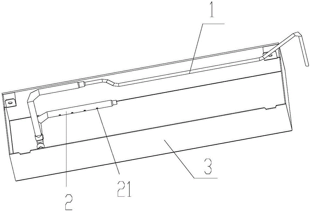
[0056] In this embodiment, on the basis of the above-mentioned embodiment 1, the water inlet pipes are replaced by several groups, and the outlet pipes 2 in each group are at least two. The water inlet pipe 1 is connected; in the system formed by the water inlet pipe 1 and the water outlet pipe 2 in the same group, the total lumen cross section of the water inlet pipe 1 is smaller than the total lumen cross section of the water outlet pipe 2 . The outlet pipe 2 is arranged parallel to the bottom of the water tank 3 , and several outlet holes 21 are arranged on the side wall of the outlet pipe 2 .
[0057] Such as figure 2 As shown, several groups of water inlet pipelines are laid flat on the bottom of the water tank 3, which can evenly heat the bottom of the water tank 3, ensuring that the cold water layer or hot water layer at the same temperature in the entire water tank 3 remains on the same level. The water outlet pipe 2 is parallel to the bottom of the water tank 3, and...
Embodiment 3
[0061] As a modification, in this embodiment, on the basis of the above-mentioned embodiment 2, the water outlet hole 21 is replaced to be inclined toward the water surface. the bezel. When the water flowing out from the water outlet hole 21 flows towards the water surface, the water retaining sheet restricts the cold water flowing out of the water outlet hole 21 in the flat gap between the water retaining sheet and the inner tank, which can effectively prevent the cold water from disturbing the hot water in the upper layer . The water inlet pipe 1 and the water outlet pipe 2 are replaced with other shapes, such as square pipes, etc. At this time, the water outlet holes 21 are opened on the side walls of the square pipes. In this embodiment, the preset distance is replaced with greater than 0, that is, there is a certain distance between the water outlet pipe and the side wall of the water tank.
PUM
 Abstract
Description
Claims
Application Information
 - R&D
- Intellectual Property
- Life Sciences
- Materials
- Tech Scout
- Unparalleled Data Quality
- Higher Quality Content
- 60% Fewer Hallucinations
Browse by: Latest US Patents, China's latest patents, Technical Efficacy Thesaurus, Application Domain, Technology Topic, Popular Technical Reports.
© 2025 PatSnap. All rights reserved.Legal|Privacy policy|Modern Slavery Act Transparency Statement|Sitemap|About US| Contact US: help@patsnap.com


