An anti-pinching device and an air-conditioning cabinet having the same
An air-conditioning cabinet machine and anti-pinch technology, which is applied to air-conditioning systems, control input related to air characteristics, mechanical equipment, etc., can solve the problems of easy hand-pinch in the outlet grille and slow response speed of the anti-pinch device, and achieve The structure is simple, the cost is low, and the effect of increasing speed
- Summary
- Abstract
- Description
- Claims
- Application Information
AI Technical Summary
Problems solved by technology
Method used
Image

Examples
Embodiment 1
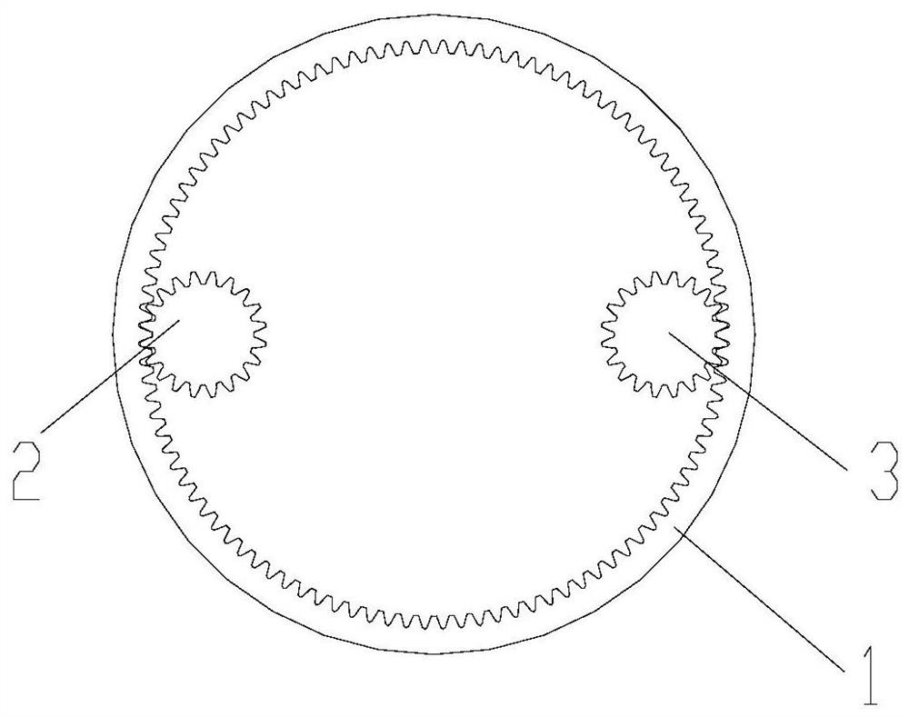
[0030] Such as figure 1 As shown, the present invention provides a quick-response anti-pinch device, which includes a rotatable first gear 1;
[0031] The detection gear 2 meshes with the first gear 1;
[0032] The light-shielding grid distribution disc 4 is circular and arranged coaxially with the detection gear 2, defining this axis as the main shaft 7, and a plurality of light-shielding grids are also arranged on the radially outer edge of the distribution disc 4 Grid bar 5 (a plurality of light-shielding grid bars form an annular light-shielding grid), and the diameter of the distribution disc 4 is greater than the diameter of the detection gear 2;
[0033] It also includes a photoelectric switch 6, which is matched with the light-insulating grid strips 5, and forms intermittent signal pulses on the photoelectric switch 6 through the shielding effect of the light-insulating grid strips 5.
[0034] In the anti-pinch device of the present invention, by setting the detectio...
Embodiment 2
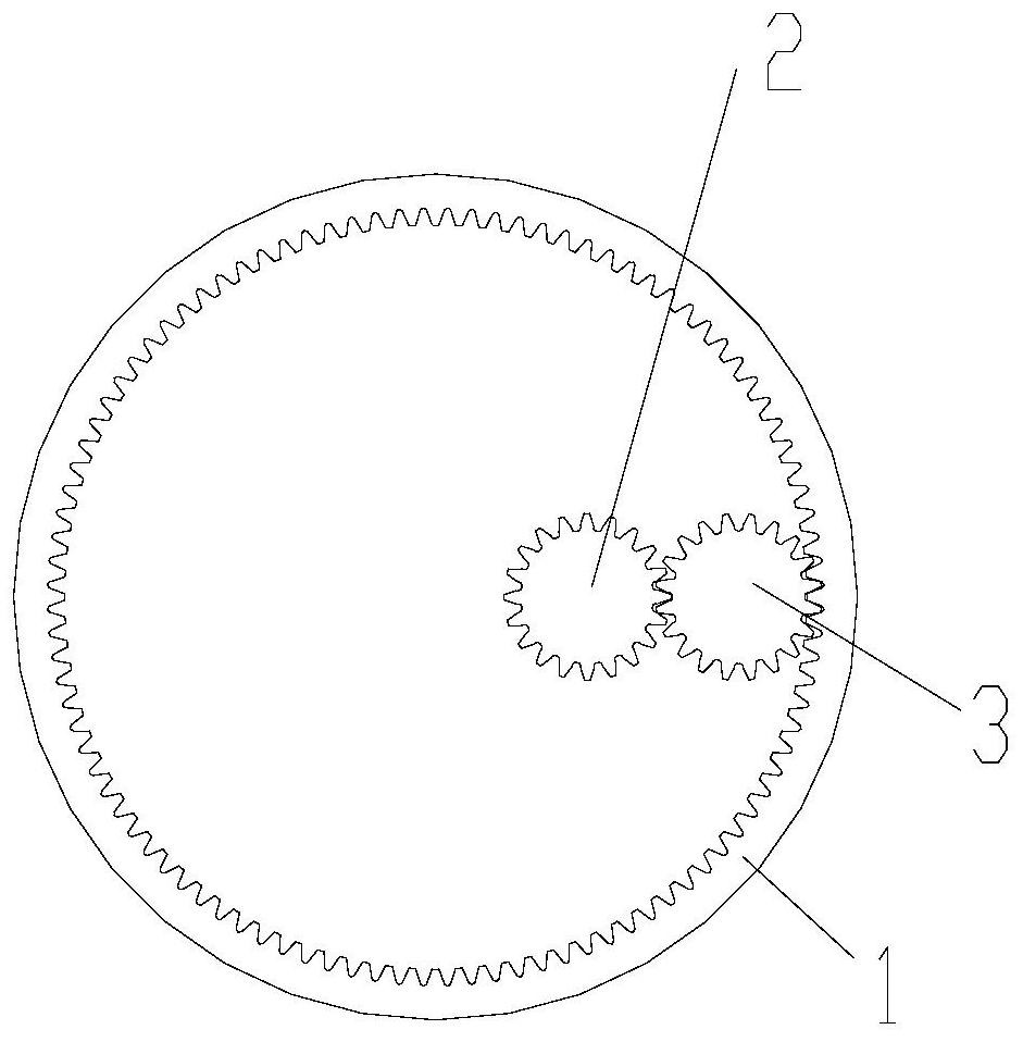
[0037] Such as figure 2 As shown, this embodiment is a transformation made on the basis of Embodiment 1, and the structural form in which the detection gear 2 meshes with the first gear 1 in Embodiment 1 is transformed into a detection gear meshing with the driving gear, and the active gear The gear is engaged with the first gear to drive the first gear to rotate.
[0038] Since the driving gear rotates in mesh with the first gear, the linear speed of rotation of the driving gear and the first gear is the same, and then the detection gear is meshed with the first gear or with the driving gear, and the result is that the detection gear is between the two. The linear speeds of rotation are the same, and combined with the coaxial arrangement of the light-shielding grid distribution disc and the detection gear, the diameter of the distribution disc is larger than the diameter of the detection gear, and finally the linear speeds of the light-shielding grid distribution discs of th...
Embodiment 3
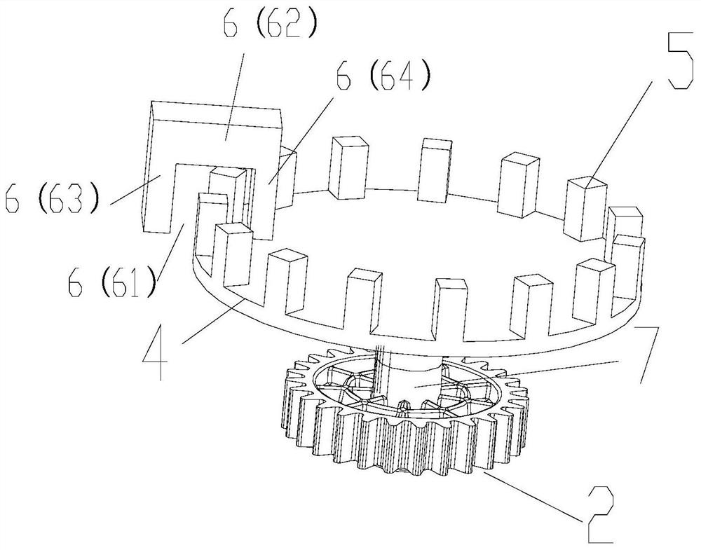
[0048] Such as image 3 As shown, this embodiment is a further improvement made on the basis of Embodiment 1 and / or 2. Preferably, the photoelectric switch 6 includes a "concave" groove structure 61; the photoelectric switch 6 also includes a horizontal Arm 62, a first side arm 63 connected to one end of the cross arm and a second side arm 64 connected to the other end, and the first side arm 63 and the second side arm 64 are parallel to each other, so that The groove structure 61 is formed between the cross arm 62 and the first and second side arms 63 and 64; the photoelectric switch 6 and the distribution plate 4 are arranged so that the distribution plate 4 can accommodate each Each of the light-shielding grating bars 5 passes through the groove structure and cuts the vertical line between the first side arm 63 and the second side arm 64 to form a discontinuous shield to generate a pulse signal. .
[0049] This is the preferred structural form of the photoelectric switch ...
PUM
 Abstract
Description
Claims
Application Information