Effect target structure for measuring peak value of impact wave pressure of movable target, and testing method

A technology of shock wave and target structure, which is applied in the direction of measuring blasting force, etc., and can solve the problems of large diameter effect target weight, error, and low resonance frequency of large diameter effect target

Active Publication Date: 2017-05-10
XIAN MODERN CHEM RES INST
View PDF9 Cites 18 Cited by
  • Summary
  • Abstract
  • Description
  • Claims
  • Application Information

AI Technical Summary

Problems solved by technology

The existing effect target has a large diameter, only a single membrane measures the pressure, the accuracy is poor, and there is not such a large calibration device to calibrate the relationship between its deformation and the shock wave load; in addition, the large diameter effect target is heavy and inconvenient to install; according to the damage Criterion, the resonant

Method used


Image

  • Effect target structure for measuring peak value of impact wave pressure of movable target, and testing method
  • Effect target structure for measuring peak value of impact wave pressure of movable target, and testing method
  • Effect target structure for measuring peak value of impact wave pressure of movable target, and testing method

Examples


Embodiment 1

[0061] In the static explosion test of 5kg spherical TNT explosive, the explosive is attached to the ground surface, and the shock wave pressure of the explosion shock wave at the effect target position is measured through the above effect target structure. Including the following steps:

[0062] Step 1: Effect target structure installation

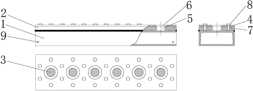
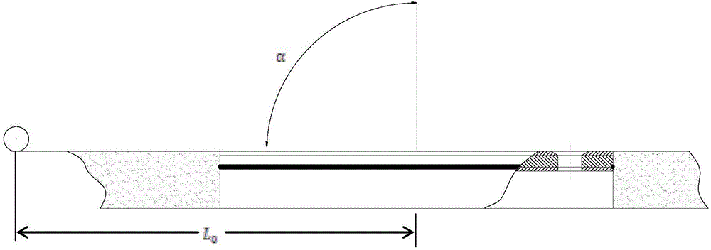
[0063] Such as figure 2 The center of the effect target shown is 3.46m away from the center of the explosive. Dig a pit on the surface where the effect target is located, place the effect target in the pit, and adjust the position so that the upper surface is flush with the ground surface;

[0064] Step 2: Read effector target data

[0065] The shock wave acts in front of the effect target, and the 6 depth values ​​of the pressure response diaphragm from the cover plate are measured with a depth gauge and recorded as H i (i=1, 2, 3, 4, 5, 6); after the shock wave acts on the effect target, use the depth gauge to measure the six depth ...

Embodiment 2

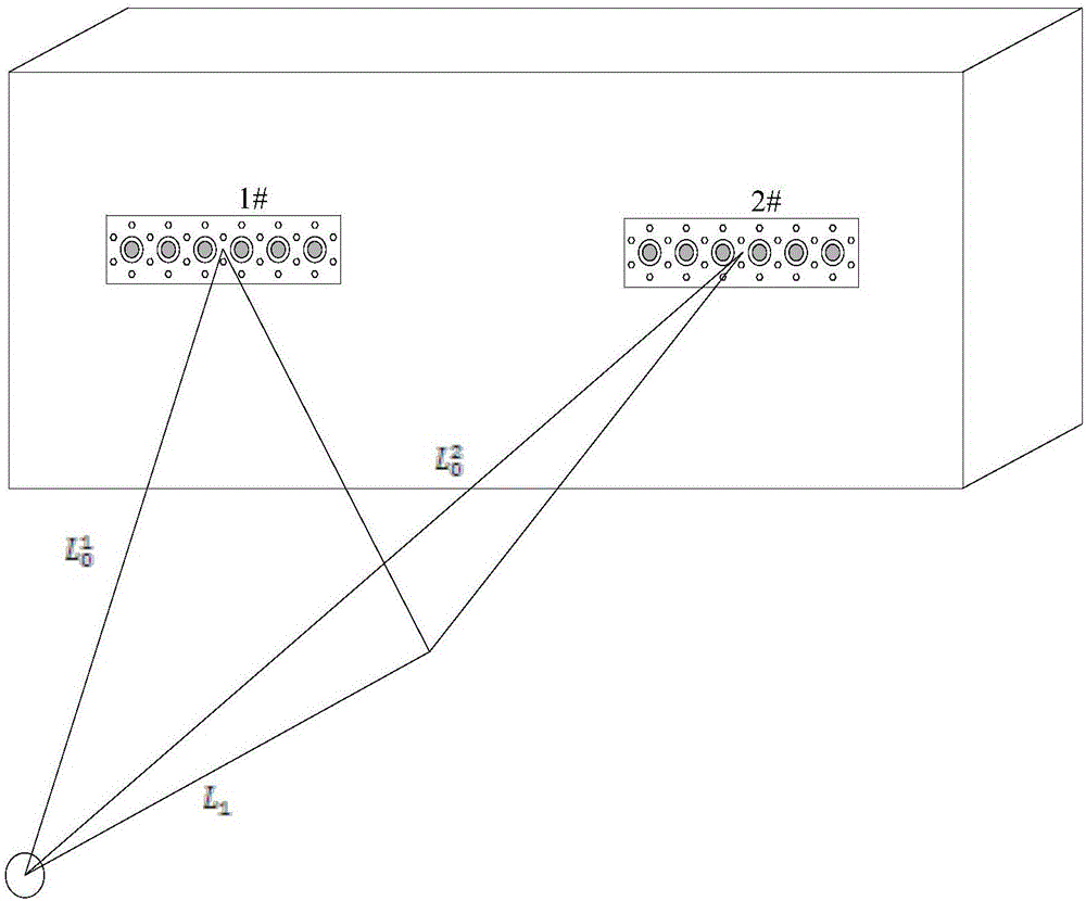
[0082] In order to obtain the damage effect of a certain explosive charge on the container target, the shock wave load on the windward side of the container is measured through the above effect target as follows: image 3 shown. The explosive is a 100Kg cylindrical TNT charge, and the explosive height is 2m. The center of the container is 15m away from the center of the explosive. The windward side of the container is perpendicular to the line connecting the explosive and the center of the container. It mainly includes the following steps:

[0083] Step 1: Effect target structure installation

[0084] Such as image 3 As shown, the effect target is connected to the container through a strong magnet, the upper surface is parallel to the windward side of the container, and the effect target is placed laterally. The installation height of the two effect targets is 1.2m, the vertical distance between the center of the 1# effect target and the container head is 1m, and the dista...


PUM

PropertyMeasurementUnit
Thicknessaaaaaaaaaa
Thicknessaaaaaaaaaa

Abstract

The invention discloses an effect target structure for measuring a peak value of an impact wave pressure of a movable target and a testing method, and belongs to the field of impact wave pressure testing. Specifically, the structure can be used for measuring the impact wave pressure of a blast field of the movable target. The structure mainly comprises a pressure response membrane installation substrate (1), a central body (2), a pressure response membrane (3), a cover plate (4), a pressure response membrane sealing groove (5), a pressure response membrane pressure leading hole (6), a bolt installation hole (7), a compression bolt (8), and a fastening connection hole (9). The invention also discloses a method for measuring the impact wave pressure and mean load of the movable target. According to the invention, the effect target structure is installed on the movable target for measuring the impact wave pressure in a target region, and obtains the impact pressure and mean load of six points in a 500mm*126mm region according to a deformation value of the pressure response membrane (3).

Description

technical field [0001] The invention belongs to the field of shock wave pressure testing, and mainly relates to a method for measuring shock wave pressure in an explosion field, in particular to an effect target structure and a testing method for measuring the peak value and average peak load of a movable target shock wave pressure. Background technique [0002] The overpressure of the explosion shock wave is an important parameter to measure the power of the explosion, and it is also an important factor that causes damage to the target. The overpressure can be measured by the equivalent pressure tank method, equivalent target plate method, biological test method, electrical measurement method, etc. At present, the electrical measurement method is widely used at home and abroad. Its advantages are high accuracy, can reflect the entire change process, and is convenient for signal storage and recording. The disadvantage is that it is easily disturbed. Factors such as high tempe...

Claims


Application Information

Patent Timeline
IPC IPC(8): G01L5/14
CPCG01L5/14
Inventor 魏巍苏健军何性顺陈君张俊锋
Owner XIAN MODERN CHEM RES INST
Why Eureka
Try Eureka