Rail transverse excitation equipment

A rail and vibration excitation technology, applied in the field of railway engineering, can solve problems such as undiscovered loading units, achieve important engineering application value, solve the effect of excessive size and accurate simulation

Inactive Publication Date: 2018-08-21
TONGJI UNIV
View PDF3 Cites 0 Cited by
  • Summary
  • Abstract
  • Description
  • Claims
  • Application Information

AI Technical Summary

Problems solved by technology

The most critical technical difficulty is how to accurately simulate the characteristics of the train load. After searching the relevant patents and scientific literature databases, at present, no loading unit with real wheel-rail geometry for the study of rail lateral excitation has been found.

Method used


Image

  • Rail transverse excitation equipment
  • Rail transverse excitation equipment
  • Rail transverse excitation equipment

Examples


Embodiment Construction

[0025] The present invention will be further described below with reference to the embodiments shown in the accompanying drawings.

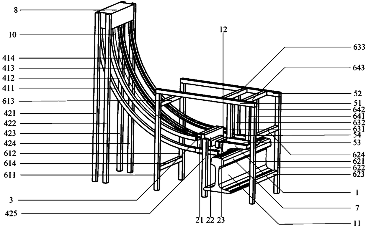
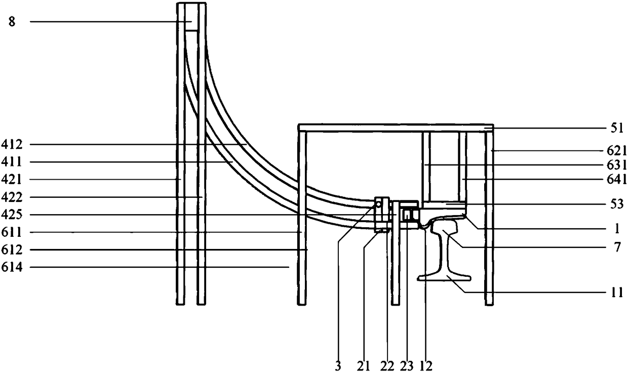
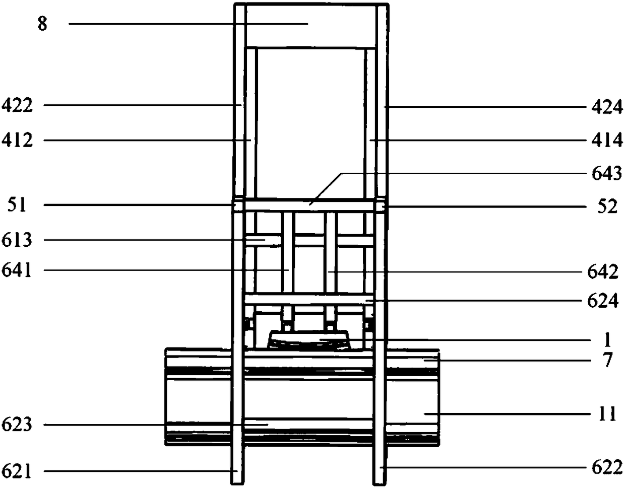
[0026] combine Figure 1 to Figure 3 As shown, the present invention first provides a rail transverse vibration excitation device, which includes a control system, a reaction force system and a loading unit, and the loading unit is respectively connected with the control system and the reaction force system.

[0027] The control system is a computer control system, which is connected with the loading unit through lines for control.

[0028] The reaction force system includes: a frame structure; a slideway formed by a first loading crank rod 411, a second loading crank rod 412, a third loading crank rod 413, and a fourth loading crank rod 414; a first loading vertical rod 421, the potential energy conversion frame formed by the second loading vertical rod 422, the third loading vertical rod 423, and the fourth loading vertical rod 424; the above-...


PUM


Abstract

The invention provides a horizontal shock excitation device for a steel rail. The horizontal shock excitation device comprises a counterforce system, a loading unit and a sensor, wherein the counterforce system comprises a potential energy switching frame and a limiting counterforce frame; a downward extending slide rail is arranged on the potential energy switching frame; the tail end of the slide rail horizontally extends out of the potential energy switching frame; the loading unit is arranged on the slide rail in a sliding form; the slide rail penetrates through the limiting counterforce frame and extends to the steel rail; a limiting counterforce surface is arranged on the limiting counterforce frame; the limiting counterforce surface is arranged right above the steel rail; the loading unit comprises a loading head for exciting the steel rail; a space for limiting the loading head is formed between the limiting counterforce surface and a sleeper of the steel rail; and the sensor is arranged on the loading unit and is used for recording and transmitting the loading data. The horizontal shock excitation device for the steel rail not only can be used for more accurately simulating a wheel rail relation but also can be conveniently operated. A test can be completed by only one person, so that the horizontal shock excitation test for the steel rail can be simply and effectively realized on site.

Description

technical field [0001] The invention belongs to the technical field of railway engineering, and relates to a lateral vibration excitation device of a rail. Background technique [0002] With the rapid development of my country's economy, my country's transportation infrastructure construction has entered a period of great development, and the operating mileage of trains has reached an unprecedented level. Therefore, it is necessary to carry out experimental research on railway line dynamics, especially on the excitation effect of track structures. Less. The most critical technical difficulty is how to accurately simulate the characteristics of the train load. After consulting the relevant patent and scientific literature databases, so far, no loading unit with real wheel-rail geometry has been found to study the lateral excitation of the rail. In in-situ testing in the field, simulating the real wheel-rail geometry is critical for test accuracy. SUMMARY OF THE INVENTION ...

Claims


Application Information

Patent Timeline
Patent Type & Authority Patents(China)
IPC IPC(8): G01M7/02
CPCG01M7/022
Inventor 金浩周顺华王毅肖军华杨新文
Owner TONGJI UNIV
Why Eureka
Try Eureka