
Automatic carrying type steel plate test robot

A robot and plate technology, applied in the direction of testing material strength by applying stable bending force, instruments, and testing material strength by applying stable tension/compression, can solve the problem of not being able to solve the problem of steel plate testing and failure to reach the test The mechanical properties of steel and the lack of high efficiency have achieved the effect of simple and easy-to-learn test operation, saving manpower and wide applicability

Active Publication Date: 2017-05-10
HEBEI INSTITUTE OF ARCHITECTURE AND CIVIL ENGINEERING
View PDF5 Cites 2 Cited by
  • Summary
  • Abstract
  • Description
  • Claims
  • Application Information

AI Technical Summary

Problems solved by technology

At present, the mechanical performance testing device for steel after perforation and steel after reinforcement is still not perfect. For example, the publication number CN205404388U discloses a camera group moving mechanism for fully automatic steel detection equipment. Automation technology is added to the detection link, but this kind of detection cannot achieve the mechanical properties of the test steel and cannot meet the above technical requirements
However, traditional mechanical testing equipment cannot efficiently and quickly adapt to the testing requirements of steel with different specifications.
[0003] In a word, the prior art products cannot well solve the problem of testing steel plates

Method used


Image

  • Automatic carrying type steel plate test robot
  • Automatic carrying type steel plate test robot
  • Automatic carrying type steel plate test robot

Examples


Embodiment 1

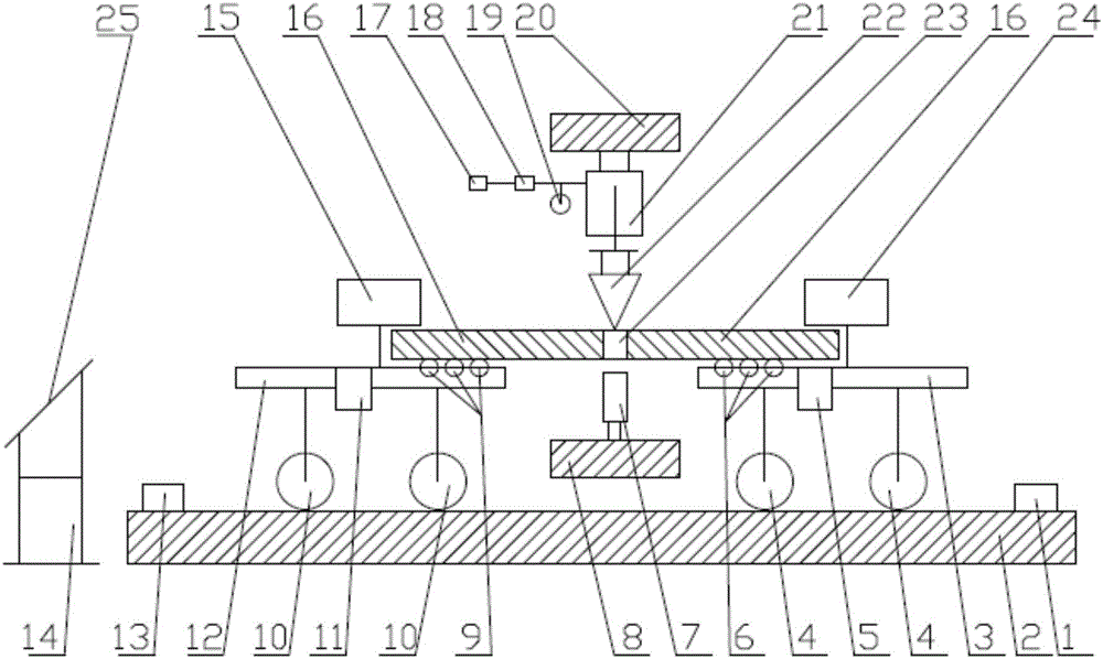
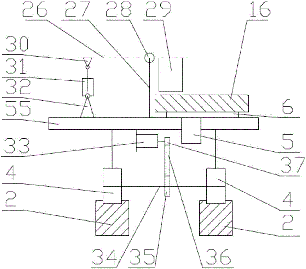
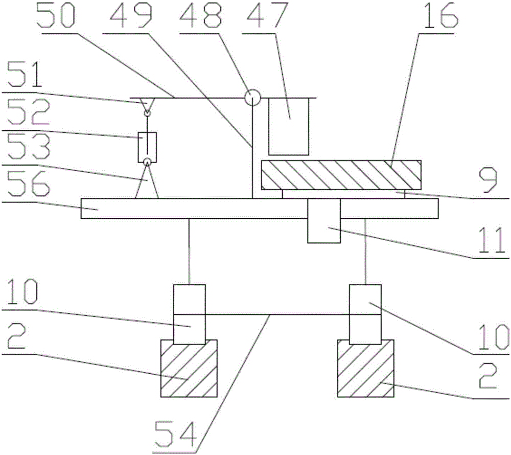
[0027] As per above figure 1 , figure 2 , image 3 , Figure 4 As shown, an automatic handling steel plate testing robot is prepared, including a guide rail 2, a guide platform 3, a follower platform 12, a testing device, and a control system; the aforementioned guide platform 3 and follower platform 12 are arranged on the guide rail 2 and can be The guide rail 2 moves left and right, the guide platform 3 is on the right, the follower platform 12 is on the left, and the test device is located on the upper side and between the guide platform 3 and the follower platform 12. The test device is used to position the steel plate 16 And apply pressure to test the bending strength of the steel plate 16; the guide platform 3 includes: guide wheel 4, roller A 6, proximity switch A 5, clamping mechanism A24, lever A 26, support rod A 27, hinge A 28, Compression block A 29, hinge support A 30, cylinder A 31, hinge support B 32, motor 33, axle A 34, timing belt wheel A 37, timing belt 36, t...

Embodiment 2

[0030] As per above Figure 5 As shown, the end of the contact 22 is designed to have a flat shape, and the flat shape can be used to test the deformation of the steel plate 16 under equal pressure. The others are the same as in Embodiment 1.

[0031] Let's take a test job as an example.

[0032] In the first step, the steel plate 16 is installed

[0033] The robot starts and completes the self-inspection. The guiding platform 3 and the following platform 12 are both on the left side of the guide rail 2. One end of the steel plate 16 is manually placed on the roller A 6 on the guiding platform working surface 55, and the steel is pushed forward Plate 16, place the steel plate 16 above the proximity switch A 5, and place the remaining part of the steel plate 16 on the roller B 9 on the working surface 56 of the follower platform to complete the installation of the steel plate 16.

[0034] The second step, automatic handling

[0035] The proximity switch A 5 detects that the steel plate...


PUM


Abstract

The invention relates to an automatic carrying type steel plate test robot, which can be used for testing the mechanical property of a steel plate before and after the reinforcement to obtain the mechanical parameter. The robot comprises a guide rail, a guide platform, a following platform, a test device and a control system. The automatic carrying in the steel plate test process can be realized; the labor is saved. Meanwhile, the robot has an automatic test function; the robot intelligently controls the steel moving position; the perforation position is automatically positioned; the mechanical property test can be automatically performed; the relevant result can be displayed; the test process is efficient and accurate; the test operation is simple and can be easily learned. The robot has a fully automatic test mode, and also has a manual test mode, so that various different use requirements can be better met. The positioning is realized through distributive color recognition sensors, the robot can be used for perforated steel plate test and can also be used for the mechanical property test of steel plates reinforced by other materials (such as carbon fiber); the application range is wide.

Description

Technical field [0001] The technical scheme of the present invention relates to an automatic testing equipment for steel plates, specifically an automatic handling type steel plate testing robot. Background technique [0002] In recent years, steel plates have been used more and more in the construction field. Due to the needs of practical applications, steel plate openings have become a common construction technology. The existence of holes changes the mechanical properties of steel plates. Reinforcing steel plates with holes through carbon fiber is an effective method, but different specifications of steel have different holes, which will lead to obvious differences in the mechanical characteristics of the steel. The differences in carbon fiber reinforcement methods will also make the reinforcement The mechanical properties of steel plates are different, so it is necessary to test the mechanical properties of the steel plates before and after reinforcement to obtain their mech...

Claims


Application Information

Patent Timeline
Patent Type & Authority Applications(China)
IPC IPC(8): G01N3/12G01N3/20
CPCG01N3/12G01N3/20G01N2203/0282G01N2203/0019G01N2203/0023G01N2203/0044
Inventor 马宏
Owner HEBEI INSTITUTE OF ARCHITECTURE AND CIVIL ENGINEERING
Learn More