
A rock joint seepage device with controllable gap width under high seepage pressure

A technology of rock joints and high permeability, which is used in measurement devices, permeability/surface area analysis, suspension and porous material analysis, etc. It can solve problems such as the geometric characteristics of rock joints, so as to avoid the phenomenon of jet flow and solve the problem of high pressure sealing.

Active Publication Date: 2019-05-14
TONGJI UNIV
View PDF6 Cites 0 Cited by
  • Summary
  • Abstract
  • Description
  • Claims
  • Application Information

AI Technical Summary

Problems solved by technology

There have been a lot of test equipment on the seepage characteristics of rock joints at home and abroad. Due to the limitation of sealing conditions, joint seepage is mostly carried out under low hydraulic gradients. In addition, most of them do not take into account the roughness of real rock joints. For example, using parallel plexiglass to simulate rock joints, or use parallel plates bonded with sand grains to simulate rock joints, neither can truly reflect the geometric characteristics of rock joints
As the two most important factors affecting the seepage characteristics of joints, joint roughness and gap width, the previous research results have not been able to study the seepage characteristics of rock joints under single factor control

Method used


Image

  • A rock joint seepage device with controllable gap width under high seepage pressure
  • A rock joint seepage device with controllable gap width under high seepage pressure
  • A rock joint seepage device with controllable gap width under high seepage pressure

Examples


Embodiment 1

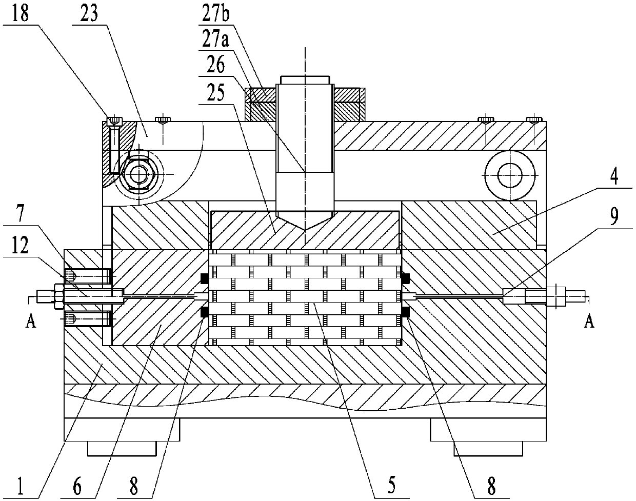
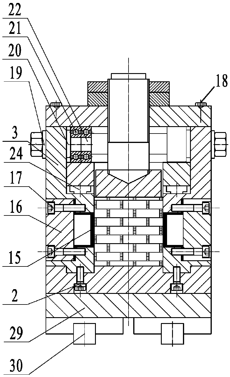
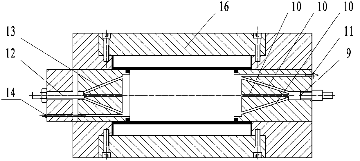
[0029] A rock joint seepage device with controllable gap width under high osmotic pressure, the device structure is as follows figure 1 and figure 2As shown, it includes a lower box body 1, two side plates 3 and an upper box body 4 fixed vertically to the lower box body 1 by vertical screws 2 arranged on both sides of the lower box body 1, the lower box body 1, the side plates 3 and the upper box body. Box body 4 is all made of stainless steel. The lower box body 1, the side plate 3 and the upper box body 4 form a cavity for placing the rock sample 5, and one end of the cavity is placed with a movable spacer 6 for fixing the rock sample 5; The fastening of the joint sample 5 in the horizontal direction can also squeeze the "back" type sealing ring 8 between the moving pad 6 and the rock joint sample 5 to ensure the sealing of the rock joint sample to both ends horizontally .


PUM


Abstract

The invention relates to a rock joint seepage device with controllable gap width under a high seepage pressure, comprising a lower box body, an upper box body, two side plates and a lifting unit; the lower box body is in the shape of reversed U; in installation, the lower box body and two side plates are encircled to be a cavity body for placing a rock sample; the middle parts of two side plates are inwards provided with linear lead rails leveled to the top part of the lower box body; the upper box body is horizontally placed on the linear lead rail, and the middle part of the upper box body is provided with a through hole with the same dimension as the top face of the rock sample; the lifting unit is connected to the top part of the rock sample by crossing through the through hole of the upper box body, a water inlet channel and a water outlet channel for interconnecting with the cavity are arranged in the lower box body. Compared with the prior art, the rock joint seepage device can provide constant high seepage pressure value in the rock joint sample seepage testing process, and realize constant pressure difference of charged and discharged water of the rock joint sample; the device can bear high seepage water pressure, has controllable joint gap width, higher testing precision, and also can simulate geological characteristics of real joints, and others.

Description

technical field [0001] The invention relates to a rock joint seepage test, in particular to a rock joint seepage device with controllable gap width under high seepage pressure. Background technique [0002] In the deep rock mass with rich groundwater, as the main water-conducting channel of the underground rock mass, the high osmotic pressure and high hydraulic gradient in the rock joints often cause high-speed seepage problems, which easily lead to pollution seepage, reservoir seepage, and tunnel seepage Water hazards in deep underground engineering. The existing research results mainly focus on the seepage characteristics of rock joints under low seepage pressure. Under high seepage pressure, due to the complex geometric characteristics of rock joints and the high-speed turbulent flow phenomenon in the seepage process, the computational complexity of numerical methods is too large. Or it is difficult to converge, the indoor seepage test is still a direct and effective mea...

Claims


Application Information

Patent Timeline
Patent Type & Authority Patents(China)
IPC IPC(8): G01N15/08
CPCG01N15/082G01N15/0826
Inventor 钱鑫夏才初桂洋黄曼庄小清喻强锋
Owner TONGJI UNIV
Learn More