Follow-up head display device and method

A technology of follow-up head and servo device, which is applied in the direction of optical components, optics, instruments, etc., can solve the problem of the brain feeling unreal

Inactive Publication Date: 2017-05-10
赵山山
View PDF1 Cites 10 Cited by
  • Summary
  • Abstract
  • Description
  • Claims
  • Application Information

AI Technical Summary

Problems solved by technology

The problem existing in the existing technology is: on the virtual reality head display, various parameters must be adjusted, including but not limited to pupil distance, eye distance, viewing distance, c

Method used


Image

  • Follow-up head display device and method
  • Follow-up head display device and method
  • Follow-up head display device and method

Examples


Embodiment 1

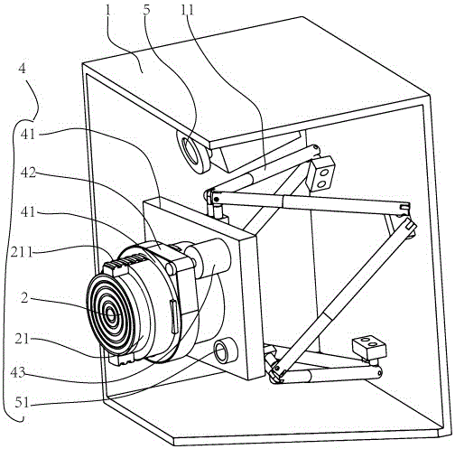
[0092] Embodiment 1, as shown in FIG. 1 , is the combined servo solution 2 of the 6-link rack servo solution. Figure 1 shows one half, say the left eye visual unit. The right eye visual unit is exactly the same as this one, just the opposite mirror image. The reason for showing half is because it is clearer and more concise. Moreover, in the rack of this example, the vision units on the left and right sides can be arranged together in one rack, or they can be arranged in separate racks that are not connected to each other. That is, the left and right racks can be connected in pairs, or can be symmetrical but not connected.

[0093] The combination in Figure 1 is a solid combination of lens and screen mechanically connected. That is to say, it is not only logically connected but also physically connected as mentioned above. The combined body has a lens, a lens holder, a combined body frame, and a screen. The lens is mounted on the lens holder, and the lens holder and the c...

Embodiment 2

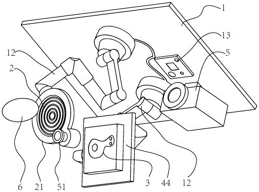
[0104] Embodiment 2, as shown in FIG. 3 , is a scheme in which the rack servo scheme of the manipulator is combined without a combination. In order to enlighten everyone, the rack in this example has become a flat panel. The rack itself does not have any limiting meaning, a flat panel can also be a rack. As long as it can install various servo devices, lenses, screens, etc., it can be called a rack. Moreover, this rack can also be provided with a servo device relative to the device connected to the head-mounted display at its upper level. Therefore, the rack is a very flexible structure. A cantilever beam can also be a rack.

[0105] This example features an articulated robotic arm mounted on a rack. Specifically, it is mechanically combined with the top, and can also be installed on the side, rear, or rear, depending on the setting of the rack plate.

[0106] In this example, the lens and the screen are integrated in control logic, but not connected in mechanical structu...

Embodiment 3

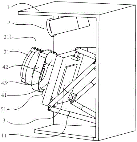
[0111] Embodiment 3, as shown in Figure 5, is the scheme of the portal frame. In this example, you can see that the rack has become a left and right united whole. In fact, both Embodiment 1 and Embodiment 2 can be like this, and of course the racks can also not be connected. The gantry is the xyz axis like a 3d printer plus rotation. There is a slit in the middle of the rack in Figure 5, which is an inspiration to everyone. This rack can be "broken" into two independent left and right.

[0112] Two conjugates can be seen in Figure 5, but the conjugate frame is absent. The rack servo device is directly installed on the screen connecting frame, and then there are three servo electric cylinders-connecting rods between the screen connecting frame and the lens seat. The configuration of these three servo electric cylinders is limited to the universal rotation degree of freedom. Linear displacement degree of freedom, that is, the three electric cylinders are always perpendicular ...


PUM


Abstract

The invention discloses a follow-up head display device, comprising an eyeball tracking device, at least two groups of servo devices, two groups of lenses and two groups of screens, wherein the left eye and the right eye respectively correspond to a group of lenses and a group of screens; an eye, a group of lenses, a group of screens and a group of servo device constitute a visual unit; the lenses of the same group and the screens of the same group can be combined into a combination, the lenses and the screens are logically a combination, the servo device connects the lenses to a frame or connects the combination of the lenses and the screens to the frame, or the four groups of servo devices respectively connect two groups of lenses and two groups of screens to the frame, the screens and/or the lenses are mobile components and are not fixed, and the combination of the lenses and the screens can be separately provided with a servo device.

Description

technical field [0001] This application belongs to the field of virtual reality head-mounted display devices. Specifically, the present application discloses a head-mounted display device and method. Background technique [0002] The virtual reality display device is a head-mounted 3D image display, which is divided into a complete helmet with its own screen and a mobile phone 3D stereo glasses using the mobile phone screen. You can refer to the records of related patents such as patent 201420529370.X that I have applied for. Some of the above patents have adjustable functions, and some do not. The problem existing in the prior art is: on the virtual reality head display, various parameters must be adjusted, including but not limited to pupil distance, eye distance, viewing distance, camera distance, and so on. Corresponding interpupillary distance and eye distance adjusting devices and the like are also respectively provided in the prior art. There are many parameters t...

Claims


Application Information

Patent Timeline
IPC IPC(8): G02B27/22
CPCG02B30/27G02B30/40
Inventor 赵山山
Owner 赵山山
Why Eureka
Try Eureka