
Display device and liquid crystal display panel

A technology for liquid crystal panels and display devices, applied in nonlinear optics, instruments, optics, etc., can solve problems such as scratches on liquid crystal panels, unfavorable thinning design of liquid crystal displays, and influence on the overall thickness of liquid crystal displays.

Pending Publication Date: 2017-05-10
WHALEY TECH CO LTD
View PDF12 Cites 0 Cited by
  • Summary
  • Abstract
  • Description
  • Claims
  • Application Information

AI Technical Summary

Problems solved by technology

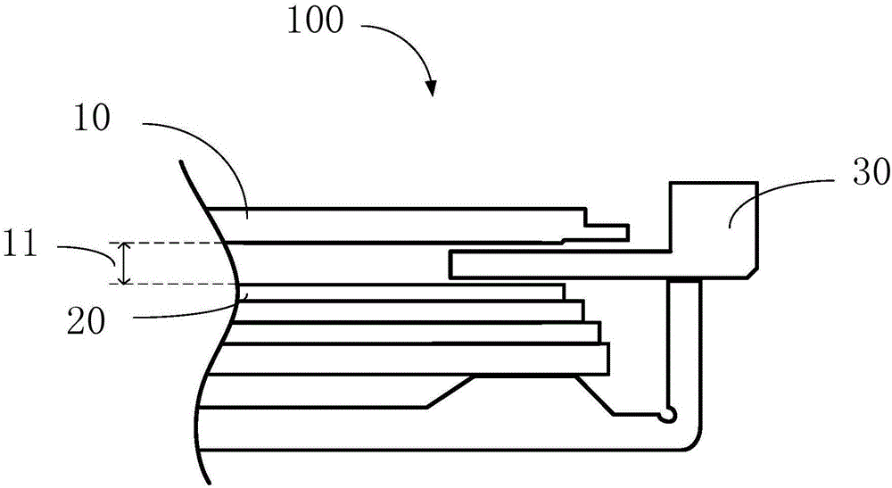
However, in the assembly process of the liquid crystal display, in order to avoid the scratch of the liquid crystal panel due to the relative movement between the liquid crystal panel and the optical film, a physical gap must be reserved between the liquid crystal panel and the optical film in the prior art
[0003] The inventor found that although the reserved physical gap can avoid scratches between the liquid crystal panel and the optical film, this physical gap will affect the overall thickness of the liquid crystal display, which is not conducive to the thin design of the liquid crystal display

Method used


Image

  • Display device and liquid crystal display panel
  • Display device and liquid crystal display panel
  • Display device and liquid crystal display panel

Examples


Embodiment Construction

[0031] The technical solutions in the embodiments of the present invention will be clearly and completely described below with reference to the accompanying drawings in the embodiments of the present invention. Obviously, the described embodiments are only a part of the embodiments of the present invention, but not all of the embodiments. The components of the embodiments of the invention generally described and illustrated in the drawings herein may be arranged and designed in a variety of different configurations. Thus, the following detailed description of the embodiments of the invention provided in the accompanying drawings is not intended to limit the scope of the invention as claimed, but is merely representative of selected embodiments of the invention. Based on the embodiments of the present invention, all other embodiments obtained by those skilled in the art without creative work fall within the protection scope of the present invention.

[0032] It should be noted ...


PUM


Abstract

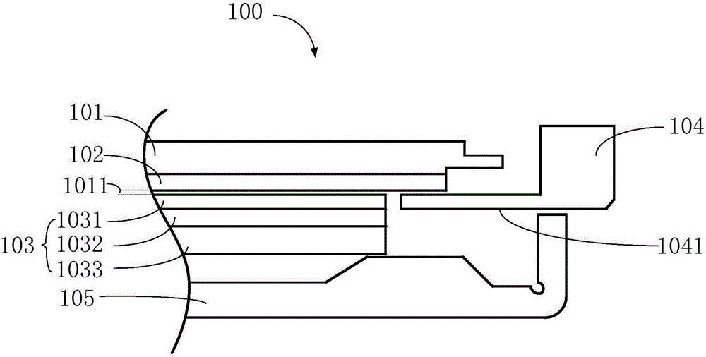
Provided are a display device and liquid crystal display panel. Gluing first optical film to the in-light surface of the LCD panel makes the first optical diaphragm and LCD panel in a relatively static state. Relative movement, scratches or other damage won't occur between first optical film and the in-light surface of the LCD panel while collision by the outside force. It is beneficial to protect the LCD panel, reduce the maintenance cost caused by the scratch problem, eliminate gap between first optical film and the in-light surface of the LCD panel, reduce the overall thickness of liquid crystal display device, and promote the ultrathin liquid crystal display device. Due to the elimination of the gap between first optical film and the LCD panel, particles in our environment will not enter into the area between first optical film and the LCD panel in assembly process, which can reduce the input of the purity of the assembly environment. Since the LCD panel has been attached to the first optical diaphragm, an optical film in assembly process is omitted, which improves the assembly efficiency.

Description

technical field [0001] The present invention relates to the technical field of liquid crystal display, and in particular, to a display device and a liquid crystal panel. Background technique [0002] During the assembly process of the liquid crystal display, in order to ensure a better display effect, it is necessary to arrange a multi-layer optical film on one side of the liquid crystal panel, such as a light enhancement film or a diffusion film, etc. These optical films are distributed with tiny optical structures. However, in the assembling process of the liquid crystal display, in order to avoid the scratching of the liquid crystal panel caused by the relative movement between the liquid crystal panel and the optical film, a physical gap must be reserved between the liquid crystal panel and the optical film in the prior art . [0003] The inventor found that although the reserved physical gap can avoid scratches between the liquid crystal panel and the optical film, the...

Claims


Application Information

Patent Timeline
IPC IPC(8): G02F1/1335
CPCG02F1/133504G02F1/133507
Inventor 薛海啸谢飞
Owner WHALEY TECH CO LTD
Learn More