Vehicle running-the-red-light detecting method and vehicle running-the-red-light detecting system

A technology of running red lights and vehicles, which is applied in the field of transportation, can solve problems such as failure to achieve results and hidden safety hazards, and achieve the effects of improving management levels, maintaining safety, and making up for the gap in punishment for running red lights

Inactive Publication Date: 2017-05-10
ZHEJIANG TENDENCY TECH
View PDF5 Cites 12 Cited by
  • Summary
  • Abstract
  • Description
  • Claims
  • Application Information

AI Technical Summary

Problems solved by technology

[0003] However, the disadvantage of this type of system is that the system can only be used for vehicles running on motor vehicle lanes, but it cannot achieve the desired effect on vehicles such as electric vehicles and motorcycles running on non-motor vehicle lanes.
[0004] Due to the underestimation of the detection and punishment of violations such as running red lights of electric vehicles, coupled with the quality of some car owners, the incidents of electric vehicles running red lights occur frequently, especially within a few seconds after the green light switches to red light and when the red light switches In the few seconds before the green light, there are great potential safety hazards

Method used


Image

  • Vehicle running-the-red-light detecting method and vehicle running-the-red-light detecting system
  • Vehicle running-the-red-light detecting method and vehicle running-the-red-light detecting system
  • Vehicle running-the-red-light detecting method and vehicle running-the-red-light detecting system

Examples


Embodiment 1

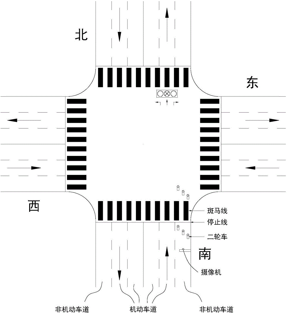
[0034] Embodiment 1, with reference to attached Figure 1-3 , a method for detecting a vehicle running a red light, comprising the following steps:

[0035] (1) Collect or identify traffic light signals;

[0036] (2) Determine the prohibited direction and the starting time and ending time of the prohibited direction;

[0037] (3) Collect or recognize the license plate number of the vehicle, the entry position of the intersection and the driving direction;

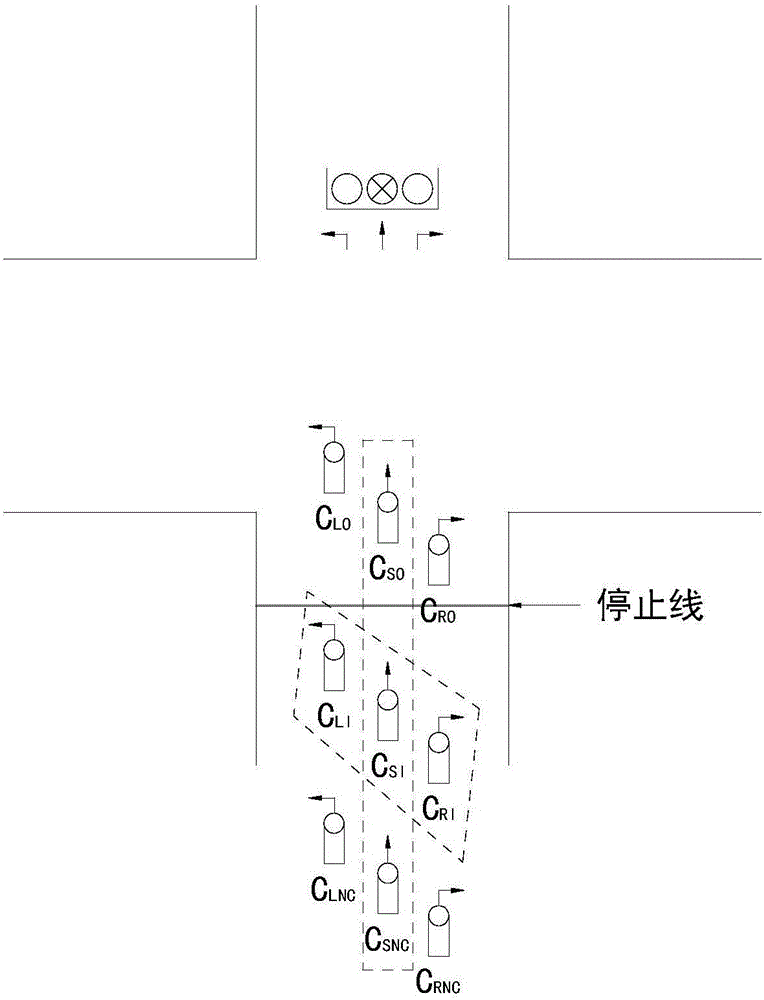
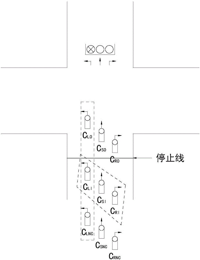
[0038] (4) Preliminarily judge whether the vehicle falls into the prohibited direction, and record the license plate number of the vehicle falling into the prohibited direction;

[0039] (5) Identify the vehicles that cross the stop line from inside to outside during the period from the start time to the end time of the prohibited direction, and the license plate numbers of such vehicles, and at the same time determine the time or time period when such vehicles are inside the stop line, and when they are in the stop line....

Embodiment 2

[0051] Embodiment 2. This embodiment is a detection system for vehicles running a red light based on Embodiment 1, including a signal label 1 installed on the vehicle, a traffic light signal detection device 2, a signal transceiving gateway 3 arranged at an intersection, and a data processing center platform 4. Camera or camera device 5;

[0052] The signal tag 1 is used to send an active wireless signal including vehicle-specific information to the signal transceiving gateway 3; the signal tag 1 includes an acceleration sensor and a geomagnetic sensor, which can also be replaced by a gyroscope; the vehicle-specific information includes the license plate number of the vehicle , the unique id number of the chip, acceleration information and orientation information; active wireless signals are sent once at predetermined intervals;

[0053] The traffic light signal detection device 2 is used to collect the traffic light signal and send it to the signal transceiving gateway 3;

...

Embodiment 3

[0059] Embodiment 3, this embodiment is another vehicle red light detection system based on Embodiment 1, including a signal label 1 installed on the vehicle, a traffic light signal detection device 2, a signal transceiving gateway 3 arranged at an intersection, and a data processing center Platform 4, camera or camera device 5;

[0060] The signal tag 1 is used to send an active wireless signal including vehicle-specific information to the signal transceiver gateway 3; the signal tag 1 is installed on the front part of the vehicle; the vehicle-specific information includes the license plate number of the vehicle and the unique id number of the chip; the active wireless signal interval is predetermined time sent once;

[0061] The traffic light signal detection device 2 is used to collect the traffic light signal and send it to the signal transceiving gateway 3;

[0062] The signal transceiving gateway 3 is used to forward the received information to the data processing cente...


PUM


Abstract

The invention relates to a vehicle running-the-red-light detecting method which comprises the following steps of (1), acquiring a traffic light signal; (2), determining a driving forbidding direction and a starting time point and an ending time point of the driving forbidding direction; (3), acquiring license plate number of the vehicle, a driving-in position in entering a crossing, and a driving direction; (4) determining whether the vehicle drives in the driving forbidding direction; (5), identifying the vehicle which passes a stopping line; (6), performing crossing comparison for determining whether vehicle running-the-red-light occurs; and (7), capturing three pictures which are in a time sequence and are separated by a certain time interval as a recording evidence of a vehicle running-the-red-light behavior. The invention further provides a vehicle running-the-red-light detecting system based on the method. The vehicle running-the-red-light detecting method and the vehicle running-the-red-light detecting system have advantages of accurately detecting the running-the-red-light rule-breaking behavior of an electric vehicle or a motorcycle or a similar vehicle at the crossing, performing a deterrence function on drivers who have relatively low quality and have a rule breaking intention, keeping safety at the crossing, improving management level of a traffic police department, and compensating a defect of incapability of performing running-the-red-light behavior punishment on two-wheeled vehicles at the existing crossing.

Description

technical field [0001] The invention relates to the traffic field, in particular to a method for detecting a vehicle running a red light and a system for detecting a vehicle running a red light. Background technique [0002] At present, almost all traffic intersections have been equipped with an automatic red light recording system, which is used for automatic detection and automatic recording and evidence collection of vehicles running red lights and other violations. Liberate a large number of police forces, reduce the labor intensity of the traffic police, improve the management level of the traffic police department, promote a virtuous circle of traffic order, reduce casualties and property losses caused by traffic accidents, and indirectly create huge economic value. [0003] Yet the weak point of this type of system is that the system can only be used for the motor vehicle running in the motor vehicle lane, but does not reach ideal effect to the vehicles running in the...

Claims


Application Information

Patent Timeline
Patent Type & Authority Applications(China)
IPC IPC(8): G08G1/017
CPCG08G1/0175
Inventor 徐承柬吴春林杨闻骏
Owner ZHEJIANG TENDENCY TECH
Why Eureka
Try Eureka