An anti-magnetic interference switching power supply and its control circuit and control method

A switching power supply and control circuit technology, applied in electrical components, output power conversion devices, AC power input conversion to DC power output, etc., can solve the problems of external strong magnetic field interference, increased cost, and bulky magnetic components, etc., to achieve Low cost, simple structure, effect of reducing interference

Active Publication Date: 2019-03-22
CHENGDU MONOLITHIC POWER SYST
View PDF2 Cites 0 Cited by
  • Summary
  • Abstract
  • Description
  • Claims
  • Application Information

AI Technical Summary

Problems solved by technology

However, when it is applied to fields such as electric meters, it will face the problem that there may be interference from external strong magnetic fields
An existing solution is to add a mechanical shielding shell to shield the interference of the external strong magnetic field on the switching power supply. The disadvantage of this method is that it increases the cost and volume
Another existing solution is to leave a very large margin when designing the magnetic components in the switching power supply, such as when designing an inductor or a transformer. This method will lead to a very large volume of the magnetic components in the switching power supply. also increased cost

Method used


Image

  • An anti-magnetic interference switching power supply and its control circuit and control method
  • An anti-magnetic interference switching power supply and its control circuit and control method
  • An anti-magnetic interference switching power supply and its control circuit and control method

Examples


Embodiment Construction

[0017] Specific embodiments of the present invention will be described in detail below, and it should be noted that the embodiments described here are only for illustration, not for limiting the present invention. In the following description, numerous specific details are set forth in order to provide a thorough understanding of the present invention. It will be apparent, however, to one of ordinary skill in the art that these specific details need not be employed to practice the present invention. In other instances, well-known circuits, materials or methods have not been described in detail in order to avoid obscuring the present invention.

[0018] Throughout this specification, reference to "one embodiment," "an embodiment," "an example," or "example" means that a particular feature, structure, or characteristic described in connection with the embodiment or example is included in the present invention. In at least one embodiment. Thus, appearances of the phrases "in on...


PUM


Abstract

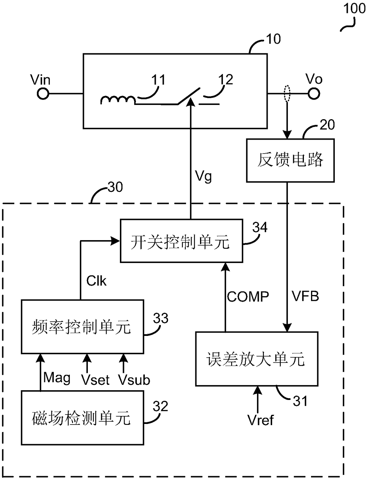
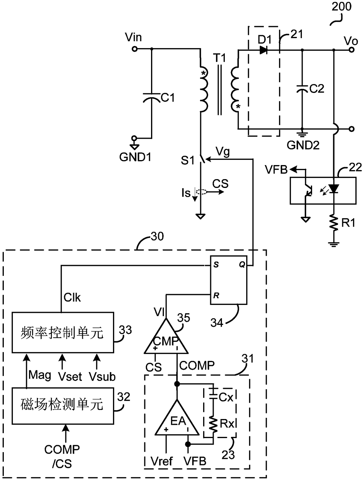
Disclosed are a switching power supply, a control circuit and a control method thereof. The control circuit includes an error amplification unit that provides an error amplification signal according to the output voltage of the switching power supply, a magnetic field detection unit that judges whether the switching power supply is affected by an external magnetic field and provides a magnetic field detection signal, a frequency control unit that provides a clock signal according to the magnetic field detection signal, and A switch control unit that provides a switch control signal to control a main power switch in the switching power supply, wherein the switch control unit controls a duty cycle of the main power switch in response to the error amplification signal and controls a switching frequency of the main power switch in response to a clock signal. Compared with the prior art, while realizing the controllable switching frequency, the interference of the external magnetic field to the switching power supply can be eliminated or weakened, and the invention has a simpler structure and lower cost.

Description

technical field [0001] Embodiments of the present invention relate to an electronic circuit, and more specifically, to a switching power supply. Background technique [0002] Switching power supply has been widely used in various fields due to its advantages such as fast transient response and low loss. However, when it is applied to fields such as electric meters, it will face the problem that there may be interference from an external strong magnetic field. An existing solution is to add a mechanical shielding shell to shield the interference of the switching power supply from the external strong magnetic field. The disadvantage of this method is that it increases the cost and volume. Another existing solution is to leave a very large margin when designing the magnetic components in the switching power supply, such as when designing an inductor or a transformer. This method will lead to a very large volume of the magnetic components in the switching power supply. It also...

Claims


Application Information

Patent Timeline
Patent Type & Authority Patents(China)
IPC IPC(8): H02M7/217H02M1/08H02M1/44
CPCH02M1/08H02M1/44H02M7/217H02M1/0003
Inventor 王斯然
Owner CHENGDU MONOLITHIC POWER SYST
Why Eureka
Try Eureka