
Resonant load circuit and a driving circuit applied to chip

A load circuit and resonance technology, applied in the direction of automatic power control, electrical components, etc., can solve the problems of clock signal noise amplitude, attenuation, etc., and achieve the effect of optimizing noise, strong suppression ability, and weakening interference and noise

Pending Publication Date: 2021-10-19
XI AN UNIIC SEMICON CO LTD
View PDF0 Cites 0 Cited by
  • Summary
  • Abstract
  • Description
  • Claims
  • Application Information

AI Technical Summary

Problems solved by technology

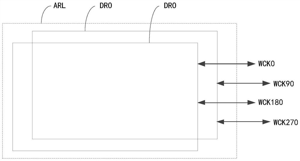
[0003] The invention provides a resonant load circuit and a drive circuit in an application chip, which can improve the problem that the clock signal is transmitted along the existing clock tree network circuit, and the clock signal is disturbed by the circuit to generate noise or amplitude attenuation

Method used


Image

  • Resonant load circuit and a driving circuit applied to chip
  • Resonant load circuit and a driving circuit applied to chip
  • Resonant load circuit and a driving circuit applied to chip

Examples


Embodiment Construction

[0051] In order to better understand the technical solutions provided by the embodiments of this specification, the technical solutions of the embodiments of this specification will be described in detail below through the drawings and specific examples. The detailed description of the technical solutions of the embodiments is not a limitation to the technical solutions of this specification. In the case of no conflict, the embodiments of this specification and the technical features in the embodiments can be combined with each other.

[0052] In this document, relational terms such as first and second etc. are used only to distinguish one entity or operation from another without necessarily requiring or implying any such relationship between these entities or operations. Actual relationship or sequence. Furthermore, the term "comprises", "comprises" or any other variation thereof is intended to cover a non-exclusive inclusion such that a process, method, article, or apparatus...


PUM


Abstract

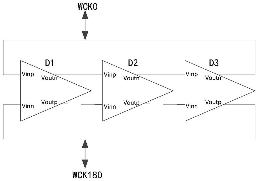
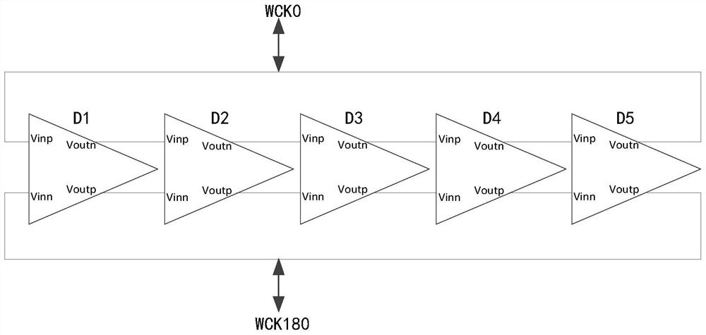
The embodiment of the invention discloses a resonant load circuit and a driving circuit applied to a chip. The resonant load circuit comprises at least one differential ring oscillation loop; each differential ring oscillation loop comprises an odd number of three or more than three delay units which are electrically connected end to end, and the delay units are used for adjusting the oscillation frequency of the differential ring oscillation loop to the frequency of a clock signal input into the differential ring oscillation loop, amplifying the amplitude of the clock signal, electrically connecting the negative phase output end of the previous delay unit with the positive phase input end of the next delay unit, electrically connecting the positive phase output end of the previous delay unit with the negative phase input end of the next delay unit, wherein the positive phase input end and the negative phase input end are used for receiving clock signals. The problem that disturbance, noise or amplitude attenuation is generated in an existing clock tree network circuit along with transmission of clock signals can be solved.

Description

technical field [0001] The present application relates to the technical field of integrated circuits, in particular to a resonant load circuit and a driving circuit in an application chip. Background technique [0002] Existing clock signal transmission circuits (also called clock tree network circuits) are usually composed of standing wave circuit units or traveling wave circuit units. The standing wave circuit unit is usually composed of CMOS (Complementary Metal Oxide Semiconductor, Complementary Metal Oxide Semiconductor). In the clock tree network circuit composed of standing wave unit circuits, a clock signal waveform can be sent and reflected at the end of the transmission line to form a sum The reflection waveform with the same frequency as the original waveform and a phase difference of 180°, the original waveform and the reflection waveform are superimposed to form a standing wave; the standing wave has the same phase at each node of the transmission line, but, wit...

Claims


Application Information

Patent Timeline
Patent Type & Authority Applications(China)
IPC IPC(8): H03L7/099
CPCH03L7/099
Inventor 马兴智贾雪绒刘成
Owner XI AN UNIIC SEMICON CO LTD
Learn More