Information equipment monitoring system with function of self-adaptive scenario virtual reality

A monitoring system and information equipment technology, applied in signal transmission system, electrical signal transmission system, three-dimensional system, etc., can solve the problem of increased labor costs, management personnel's inability to intuitively and comprehensively understand the operating status information of the computer room, and increased maintenance personnel occurrences, etc. problem, to achieve the effect of low system overhead

Active Publication Date: 2017-05-10
STATE GRID CORP OF CHINA +1
View PDF6 Cites 26 Cited by
  • Summary
  • Abstract
  • Description
  • Claims
  • Application Information

AI Technical Summary

Problems solved by technology

[0003] 1. Most of the computer room management systems currently use traditional text or two-dimensional graphic interactive interfaces. Managers cannot intuitively and comprehensively understand the current computer room environment and operating status information, which is not conducive to convenient remote management
[0004] 2. For an unattended computer room, when a fault occurs, the existing computer room management system can only know the number of the equipment that has the problem, and cannot quickly locate the specific location and site conditions of the faulty equipment. Maintenance personnel need to check the equipment in the computer room , which increases the possibility of injury for maintenance personnel exposed to strong electromagnetic environments
[0005] 3. For equipment changes and configuration changes in the computer room, they cannot be automatically changed in the system, and manual updates are required, which increases labor costs

Method used


Image

  • Information equipment monitoring system with function of self-adaptive scenario virtual reality
  • Information equipment monitoring system with function of self-adaptive scenario virtual reality
  • Information equipment monitoring system with function of self-adaptive scenario virtual reality

Examples


Embodiment Construction

[0019] Specific embodiments of the present invention will be described in detail below, and it should be noted that the embodiments described here are only for illustration, not for limiting the present invention. In the following description, numerous specific details are set forth in order to provide a thorough understanding of the present invention. It will be apparent, however, to one of ordinary skill in the art that these specific details need not be employed to practice the present invention. In other instances, well-known circuit structures, systems or methods have not been described in detail in order to avoid obscuring the present invention.

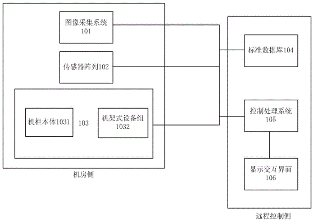
[0020] figure 1 A frame diagram of an information device monitoring system 100 according to an embodiment of the present invention is shown. Such as figure 1 As shown, the information equipment monitoring system 100 includes: an image acquisition system 101, which is arranged on the side of the computer room, and is used to ...


PUM


Abstract

The invention discloses an information equipment monitoring system. The information equipment monitoring system comprises an image acquisition system, a sensor array, a cabinet array, a standard database, and a display and interaction interface system, wherein the image acquisition system, the sensor array and the cabinet array are arranged on a computer room side; the standard database and the display and interaction interface system are arranged on a remote control side; and a control and processing system is connected to the image acquisition system, the sensor array, the cabinet array and the standard database, generates an initial three-dimensional rendering model of a computer room as a virtual reality interaction interface according to signals sent back by the image acquisition system and a standard three-dimensional model in the standard database, and carries out processing according to the signals sent back by the image acquisition system, the sensor array and the cabinet array and with reference to data in the standard database to generate onsite monitoring data for the computer room. The information equipment monitoring system provided by the invention has the advantages that onsite information and the working status of the computer room can be genuinely displayed in the form of three-dimensional rendering virtual reality in a display and interaction interface with lower system expenses, and switching to an onsite video can be carried out whenever necessary, so that a current computer room environment and current equipment statuses can be monitored visually.

Description

technical field [0001] The present invention relates to the field of electronic systems. More specifically, the present invention relates to an information equipment monitoring system. Background technique [0002] With the continuous progress and development of information technology, especially Internet technology, the construction of data centers and computer rooms (including substation computer rooms, collectively referred to as computer rooms) in various industries is developing rapidly, and the number of computer room points and cabinet equipment has increased sharply. The better the momentum. However, at the same time, there are also prominent problems in computer rooms in various industries, such as lack of overall planning and long-term planning, coexistence of new and old equipment, and poor compatibility. As a result, the current computer room operation and maintenance management and control capabilities are weak and the degree of automation is low. Specifically...

Claims


Application Information

Patent Timeline
Patent Type & Authority Applications(China)
IPC IPC(8): H04N7/18H04N13/02H04N13/04G06F3/01G06T17/00G06T19/00G08C19/00
CPCG06F3/011G06T17/00G06T19/00G06T2200/08G08C19/00H04N7/18H04N13/239H04N13/332H04N13/359
Inventor 吴珺刘明峰李文坤田小川侯路郭顺森韩然李祥新
Owner STATE GRID CORP OF CHINA
Why Eureka
Try Eureka