Device For Connecting Strip Ends Of Steel Strips

A strip and steel technology, applied in welding equipment, laser welding equipment, metal processing equipment, etc., can solve the problems of lowering the quality of final products, lowering the quality of intermediate products, lowering the quality of continuous strip processing, etc. Effects of calibration, compact design, reliable location

Inactive Publication Date: 2017-05-10
SMS GRP GMBH
View PDF9 Cites 5 Cited by
  • Summary
  • Abstract
  • Description
  • Claims
  • Application Information

AI Technical Summary

Problems solved by technology

Such defects reduce the quality of the intermediate product and thus also the final product and also reduce the quality of the handling of the continuous strip

Method used


Image

  • Device For Connecting Strip Ends Of Steel Strips
  • Device For Connecting Strip Ends Of Steel Strips
  • Device For Connecting Strip Ends Of Steel Strips

Examples


Embodiment Construction

[0028] A preferred embodiment is described below with reference to the drawings. In this case, identical, similar or identically acting elements are identified by the same reference numerals in different figures and a repeated description of these elements is partially omitted in order to avoid a redundant description.

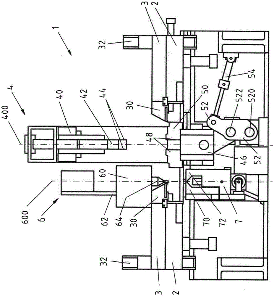
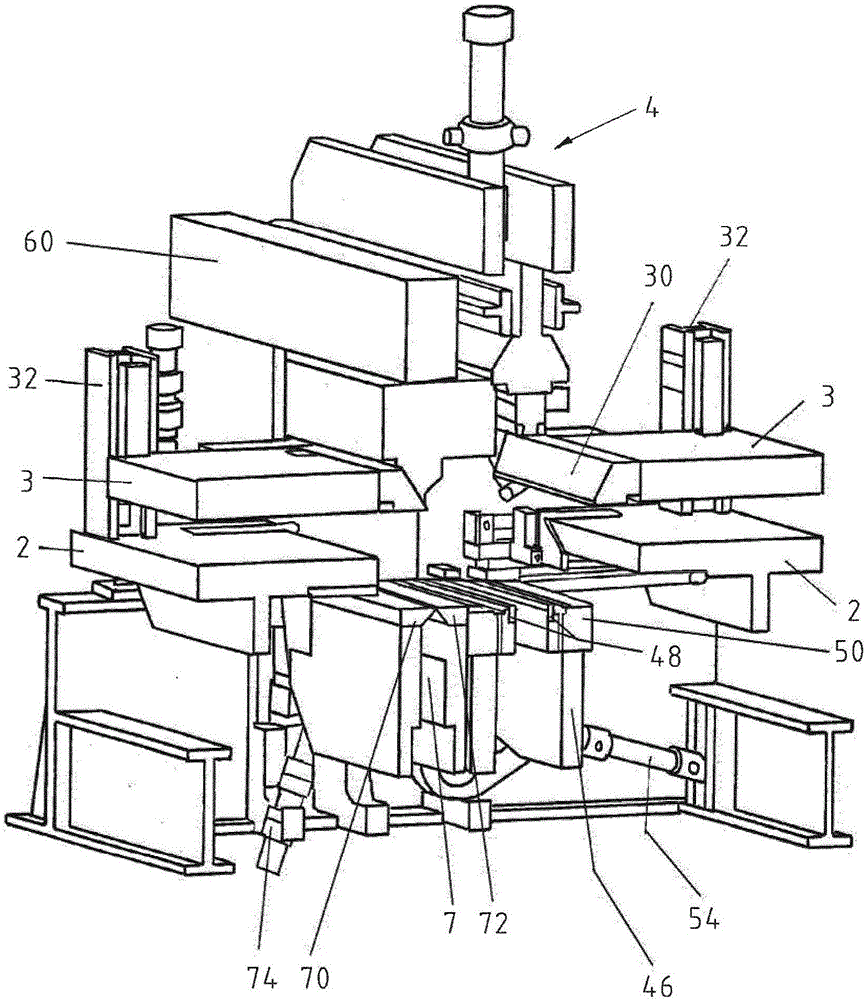
[0029] figure 1 A device 1 for joining strip ends is shown, which device is provided with a shear 4 . An upper blade support 40 with an upper blade 44 is arranged above the horizontal plane of the transport strip. The upper blade holder 40, which includes the upper blade 44 in the upper blade case 42, is movable along its vertical axis by a hydraulic system. Arranged below the upper blade holder 40 along the vertical axis is a lower blade holder 46 comprising a lower blade case 50 with a lower blade 48 . The upper blade case 42 can be lowered by the upper blade holder 40 and closed with the lower blade case 50 in the cutting position.

[0030] In order to ...


PUM


Abstract

The present invention relates to a device 1 and a method for connecting strip ends of steel strips, having shears 4, wherein the shears 4 comprise an upper blade carrier 40 having one or more upper blades 44 and a lower blade carrier 46 having one or more lower blades 48, a welding appliance 60, at least one welding table 70, 72 and side parts 2 for horizontally moving the strip ends, wherein the welding appliance 60 and the shears 4 are separated from one another in their planes of action.

Description

technical field [0001] The invention relates to a device for joining strip ends of steel strips. Background technique [0002] For processing the metal strip it is advantageous if the metal strip is present in as long a form as possible. Optimally, there is a so-called continuous strip, since in this continuous strip the treatment can be carried out continuously. After the continuous strip has been processed on the continuous processing line, the continuous strip is cut open again. Continuous strip is produced by joining or joining finite lengths of steel strip. In the joining process of strips, two factors are particularly important: the speed of the joining and the quality of the welding or joining. The speed of the connection is the duration required to connect the ends of the strip. It is a factor that determines production and has great significance for subsequent processes. A co-determining factor is the quality of the welding, which limits the shortest possible t...

Claims


Application Information

Patent Timeline
Patent Type & Authority Applications(China)
IPC IPC(8): B23K26/26
CPCB23K26/26
Inventor J·阿特尔S·阿利帕斯M·本德勒C·多恩沙伊特L·屈梅尔C·温特
Owner SMS GRP GMBH
Why Eureka
Try Eureka