Thermostatic valve having a sleeve

A thermostatic valve and sleeve technology, applied in the field of thermostatic valves, can solve the problems of unbalanced obturators, deformation of sealing rings, weak valve design, etc., and achieve the effect of convenient assembly

Inactive Publication Date: 2017-05-10
VERNET SA
View PDF10 Cites 1 Cited by
  • Summary
  • Abstract
  • Description
  • Claims
  • Application Information

AI Technical Summary

Problems solved by technology

However, the sealing ring is arranged such that it forms an unbalanced obturator, that is to say the pressure difference on both sides of its peripheral wall does not have a zero value
Therefore, there is a fear that the sealing ring may deform, or even break when the valve is integrated into the cooling circuit of a heavy engine with high cooling fluid flow rates
Therefore, this type of valve design is not robust

Method used


Image

  • Thermostatic valve having a sleeve
  • Thermostatic valve having a sleeve
  • Thermostatic valve having a sleeve

Examples


Embodiment Construction

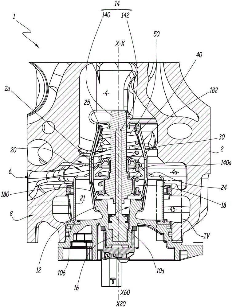
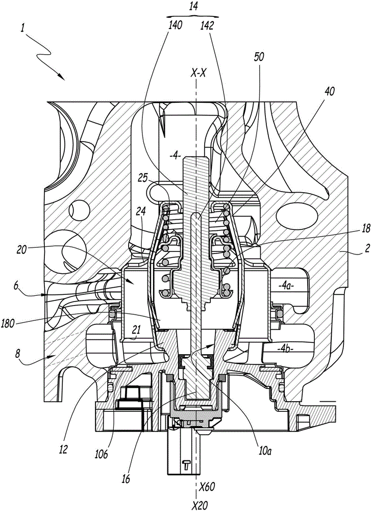
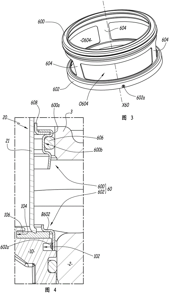
[0025] exist figure 1 In Fig. 4, a thermostat 1 is shown capable of regulating and controlling the circulation of cooling fluid. In this context, fluid means a liquid, or even a two-phase mixture. The valve 1 is used, for example, in a cooling circuit for cooling an internal combustion engine of a vehicle.

[0026] The valve 1 comprises a valve body 2 for guiding fluid. The body 2 defines a communication central duct 4 for fluid to flow therethrough. The central duct 4 extends along the longitudinal axis X-X.

[0027] In the following part of the specification, the terms "high / upper", "low / lower", "top / upper" and "bottom / lower" shall be used relative to the longitudinal axis X-X in figure 1 and figure 2 explained in the structure. exist figure 1 and figure 2 Among them, the central pipe 4 extends downward to the bottom, and includes a first chamber 4A and a second chamber 4B located below the chamber 4A. The valve body 2 delimits two further ducts 6 and 8 which open...


PUM


Abstract

The invention relates to a thermostatic valve including a body (2), which defines a first pipe for fluid to flow therethrough, and into which at least a second pipe and at least a third pipe transversely lead, a sleeve (20), which is movable inside the valve body so as to place at least one of the second and third pipes in communication with the first pipe, a thermostatic element, including a stationary portion and a movable portion which is movable as a result of a change in the volume of a heat-expansible material contained in the thermostatic element and which is translatably connected to the sleeve, a housing (10) for supporting the thermostatic element, which is rigidly connected to the stationary portion of the thermostatic element, which is immobilised inside the first pipe, and which sealingly engages with the sleeve, and a sealing ring (60) between the sleeve and the valve body. The housing (10) seals one end of the first pipe and the sealing ring (60) is fixedly connected to the housing (10) for supporting the thermostatic element and comprises at least one opening for the fluid to flow through the body thereof.

Description

technical field [0001] The invention relates to a thermostatic valve for a fluid circulation system, in particular for circulating a cooling fluid for cooling an internal combustion engine. Background technique [0002] Valves provided with a modulating control sleeve whose movement is controlled by a thermostatic element are usually equipped with a cooling circuit associated with internal combustion engines with high engine cylinder capacities, especially those used in trucks and certain motor vehicles, the operation of which requires The flow rate of the coolant fluid is higher than that faced by an internal combustion engine with a lower engine cylinder capacity in which the thermostatic valves used have flap gates. [0003] In fact, the use of sleeves can often have supposedly (pressure) balanced obturators (gates, plugs), that is to say, on both sides of the sleeve wall in the direction of movement of the sleeve by the thermostatic element. For an obturator with a pres...

Claims


Application Information

Patent Timeline
Patent Type & Authority Applications(China)
IPC IPC(8): G05D23/02F01P7/16
CPCF01P7/16G05D23/022
Inventor 奥德·波斯特纳克蒂埃里·马罗
Owner VERNET SA
Why Eureka
Try Eureka