
Clamping mechanism for precision small modulus gear

A small-modulus gear and clamping mechanism technology, which is used in gear cutting machines, components with teeth, gear tooth manufacturing devices, etc., can solve the problems of wear and scrap of small-modulus gears

Inactive Publication Date: 2017-05-17
CHONGQING DAIFA CASTING
View PDF8 Cites 2 Cited by
  • Summary
  • Abstract
  • Description
  • Claims
  • Application Information

AI Technical Summary

Problems solved by technology

[0006] The purpose of the present invention is to provide a clamping mechanism for precision small modulus gears to solve the problem that small modulus gears are easily worn and scrapped due to excessive clamping force

Method used


Image

  • Clamping mechanism for precision small modulus gear
  • Clamping mechanism for precision small modulus gear

Examples


Embodiment

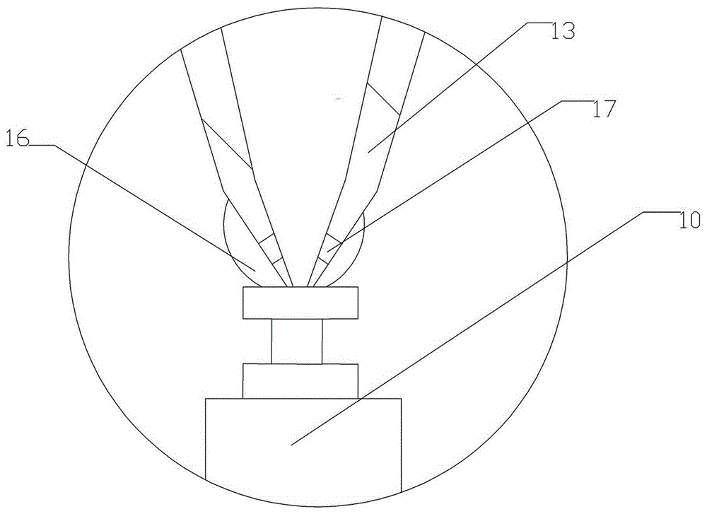
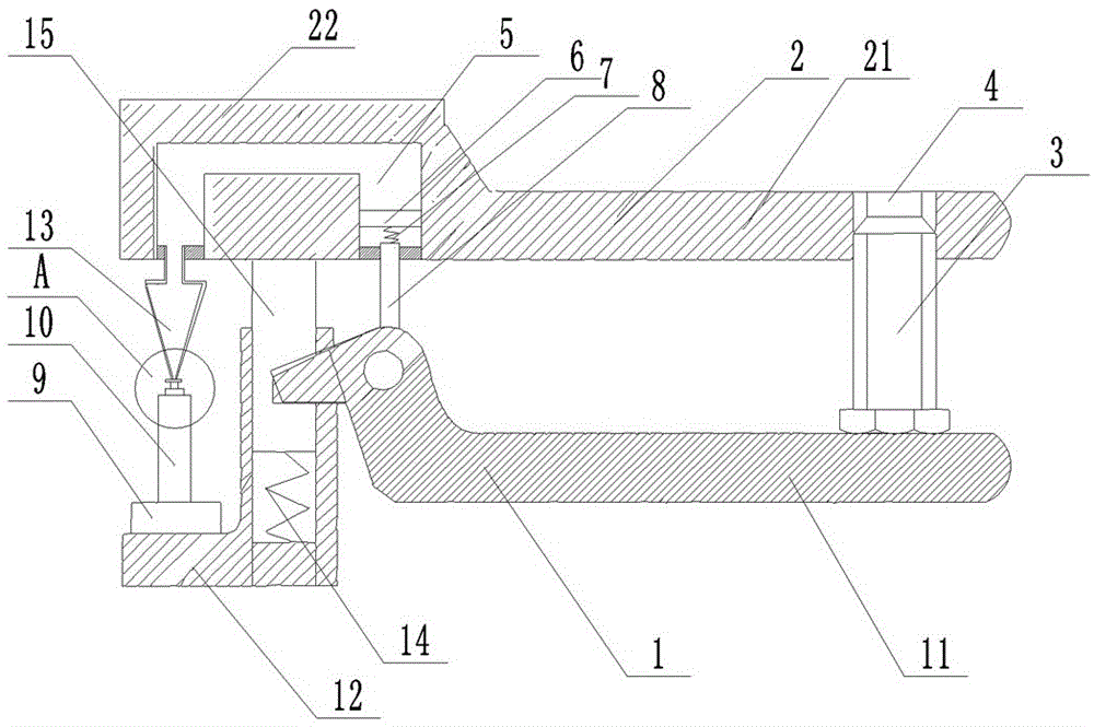
[0019] Basic as attached figure 1 As shown: the clamping mechanism of the precision small modulus gear 10 in this solution includes the fixed arm 1 below and the movable arm 2 above. The fixed arm 1 includes a clamping part 12 and a hand-held part 11. The clamping part 12 The left side is connected with a support seat 9 through a bearing, and a groove is provided on the support seat 9, and a small modulus gear 10 is placed in the groove, and a round hole is opened on the right side of the clamping part 12, and a first spring 14 is welded at the bottom of the round hole. The top of the first spring 14 is welded with a sliding shaft 15, the top of the sliding shaft 15 is in contact with the short arm 22 of the movable arm 2, the sliding shaft 15 is hinged with the integrally formed protrusion at the left end of the handle 11, and the right end of the handle 11 is rotatably connected with a fine-tuning screw 3. The fine-tuning screw 3 is screwed into the threaded hole 4 of the lo...


PUM


Abstract

The invention belongs to the technical field of gear deburring equipment and particularly discloses a clamping mechanism for a precision small modulus gear. The clamping mechanism comprises a fixed force arm and a movable force arm, wherein the fixed force arm comprises a handheld part and a clamping part; a protrusion is arranged at one end of the handheld part; the surface of the clamping part is rotationally connected with a supporting base; the small modulus gear is arranged on the supporting base; the clamping part is provided with a vertical round hole; a first spring is arranged at the bottom of the round hole; the top end of the first spring is connected with a sliding shaft; the top end of the sliding shaft abuts against the movable force arm; the sliding shaft is hinged to the clamping part; the movable force arm comprises a long arm body and a short arm body; a cavity is formed in the short arm body and filled with hydraulic oil; an extrusion device is arranged at the end, opposite to the handheld part, of the cavity and abuts against the protrusion; a centre is connected with the end, opposite to the clamping part, of the cavity; an air bag is arranged at the bottom of the centre; through holes are formed in the side wall of the bottom of the centre and located inside the air bag; and clamping force can be increased through soft compression by the air bag, and the rate of the finished small modulus gear is improved.

Description

technical field [0001] The invention belongs to the technical field of gear deburring equipment. Background technique [0002] Small modulus gears refer to gears with a modulus less than 1mm, which are widely used in aviation machinery, electronic products, precision machinery, instruments and timing mechanisms. Due to the small size and high precision requirements of small modulus gears, after forming Deburring and polishing are required, and the commonly used equipment is deburring machines and rolling polishing machines, as well as simple bow-shaped clamping tools. Deburring machines and rolling polishing machines are suitable for mass production, but they are easy to damage the gear surface and the processed shape and dimension accuracy; simple manual hand-held bow clamp tools are labor-intensive, easy to fatigue hands, unreliable clamping, and parts are easy to fly out and bump Damaged parts, the tip of the bow clamp is a fixed shaft, which rubs against the tip hole of...

Claims


Application Information

Patent Timeline
Patent Type & Authority Applications(China)
IPC IPC(8): B23F23/06
CPCB23F23/06
Inventor 唐利
Owner CHONGQING DAIFA CASTING
Learn More