
Automatic unpacking and unloading method

An automatic, material-packing technology, which is applied in the directions of packaging, transportation, packaging, and unsealing of packaged objects, can solve the problems of easy mixing of materials, waste of residual materials, and debris of packaging bags, etc., and achieve the effect of reducing consumption and preventing waste of raw materials

Inactive Publication Date: 2017-05-17
CHINA JILIANG UNIV
View PDF7 Cites 0 Cited by
  • Summary
  • Abstract
  • Description
  • Claims
  • Application Information

AI Technical Summary

Problems solved by technology

For the granular material package, Italy has developed an automatic feeding and cutting system for the polymer particle material package, which uses a manipulator to move the material package to a special cutter head bag breaker, then puts the material bag down, and the material bag falls to the cutter head This system is easy to break the woven bag and cause the problem that the woven bag debris pollutes the raw material
Similarly, some domestic automatic unpacking devices also have this problem, such as Chinese patent CN2015103809614 and patent CN2015103540947, both use saw blades to destructively unpack bags, which is prone to bag debris
[0004] Chinese patent CN2015108873053 has improved this problem. When the bag is broken, the bag debris will not fall into the material pool with the material, but it still has the incomplete whereabouts of the material in the material bag, and it is easy to fall into the folds and corners of the material bag. The problem of residual material
[0005] It can be seen that the automatic unpacking and feeding device in the prior art often produces packaging bag debris, which is easily mixed into the material, and the incomplete whereabouts of the material causes the problem of waste of residual material

Method used


Image

  • Automatic unpacking and unloading method
  • Automatic unpacking and unloading method
  • Automatic unpacking and unloading method

Examples


Embodiment Construction

[0029] Preferred embodiments of the present invention will be described in detail below with reference to the accompanying drawings, but the present invention is not limited to these embodiments. The present invention covers any alternatives, modifications, equivalent methods and schemes made within the spirit and scope of the present invention.

[0030] In order to provide the public with a thorough understanding of the present invention, specific details are set forth in the following preferred embodiments of the present invention, but those skilled in the art can fully understand the present invention without the description of these details.

[0031] In the following paragraphs the invention is described more specifically by way of example with reference to the accompanying drawings. It should be noted that all the drawings are in simplified form and use inaccurate scales, which are only used to facilitate and clearly assist the purpose of illustrating the embodiments of t...


PUM


Abstract

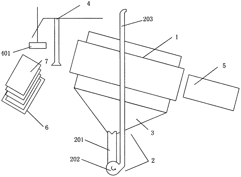
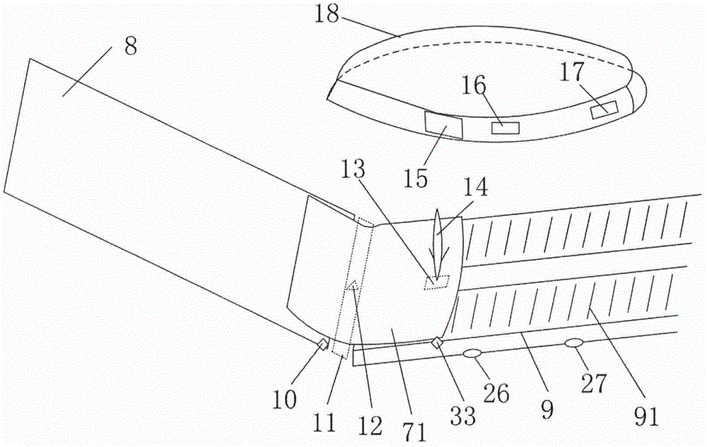
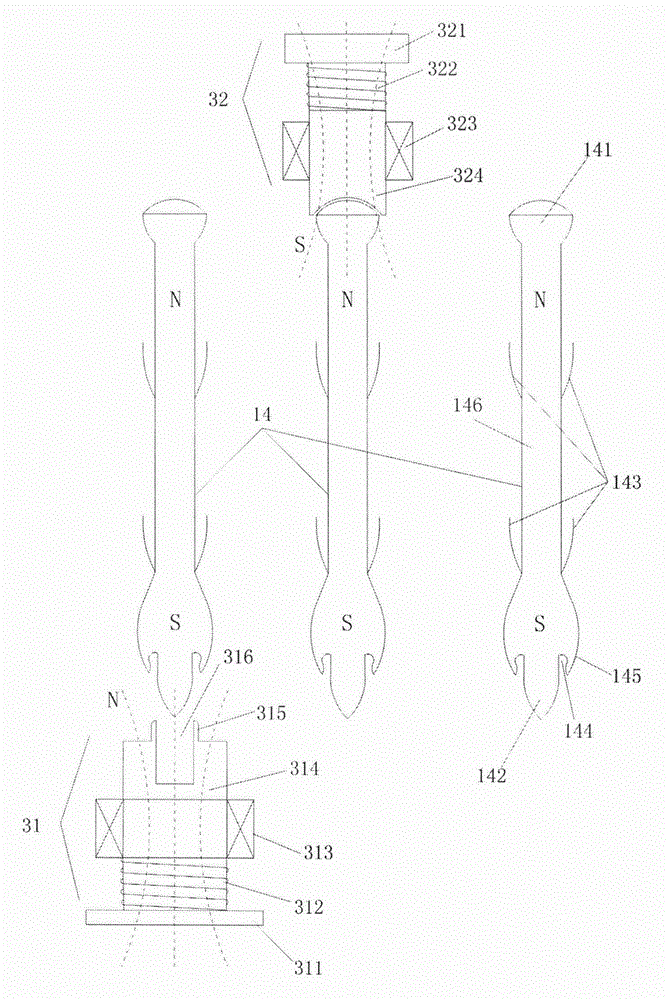
The invention discloses an automatic unpacking and unloading method. A conveying belt is adopted to convey material packages, and is provided with a material package sensor for detecting the material packages and a magnetic needle head matching body matched with a magnetic needle head part; when the material packages are conveyed to a preset position, a cutting mechanism is adopted to cut and unpack the material packages; a package lifting mechanism is arranged above the conveying belt, and is provided with a magnetic needle emitting mechanism and a magnetic needle tail matching body matched with a magnetic needle tail part in sequence; when a magnetic needle is in an initial state, the magnetic needle is positioned in the magnetic needle emitting mechanism; in the conveying process of the cut and unpacked material packages, after the material package sensor detects the positions of the material packages, the magnetic needle emitting mechanism emits out the magnetic needle onto the material packages, and the magnetic needle head part is matched with the magnetic needle head matching body; and the magnetic needle tail matching body on the package lifting mechanism sucks the magnetic needle to realize lifting of the material packages. The automatic unpacking and unloading method realizes automatic unpacking, cannot generate the packing bag chip pollution to particles, realizes no-residue falling, and prevents raw material wastes.

Description

technical field [0001] The invention relates to the technical field of automatic feeding, in particular to an automatic unpacking and unloading method for industrial production. Background technique [0002] The main raw material for the production of plastics (such as biaxially oriented film BOPP) is polymer particle PP material, which is generally packed and transported in woven bags. At present, most of the feeding of granular materials in China is done manually, and there are many disadvantages in manual feeding. First of all, manual feeding seriously reduces the degree of automation of the process, and manual unpacking is labor-intensive and prone to fatigue, resulting in unstable feeding speed, which is prone to problems that the manual speed cannot keep up with supporting equipment; secondly, material bag feeding and cutting is a heavy task. It is tedious manual labor, and it is difficult for manual feeding to be efficient and smooth all-weather. Therefore, the plas...

Claims


Application Information

Patent Timeline
Patent Type & Authority Applications(China)
IPC IPC(8): B65B69/00
CPCB65B69/0008B65B69/0033
Inventor 邹细勇王月真胡晓静
Owner CHINA JILIANG UNIV
Learn More