Driving device for changing fan rotating direction and control method

A technology of rotation direction and driving device, which is applied in the control of coolant flow, engine cooling, engine components, etc., and can solve the problems of high manufacturing cost and complex structure

Active Publication Date: 2017-05-17
LONGKOU ZHONGYU THERMAL MANAGEMENT SYST SCIAND TECH
View PDF5 Cites 6 Cited by
  • Summary
  • Abstract
  • Description
  • Claims
  • Application Information

AI Technical Summary

Problems solved by technology

However, this scheme is complex in structure and high in manufacturing cost

Method used


Image

  • Driving device for changing fan rotating direction and control method
  • Driving device for changing fan rotating direction and control method
  • Driving device for changing fan rotating direction and control method

Examples


Embodiment Construction

[0091] The present invention is described in detail below with reference to accompanying drawing and embodiment:

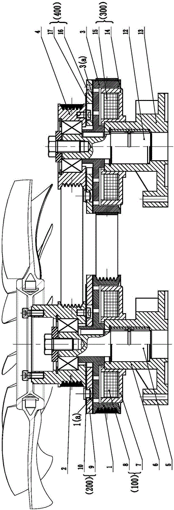
[0092] Figure 5 It is a working diagram of the first embodiment of the driving device for changing the rotation direction of the fan, the first clutch is in the engaged state, the second clutch is in the disengaged state, and the fan rotates counterclockwise.

[0093] Image 6 It is a schematic diagram of the operation of the first embodiment of the driving device for changing the rotation direction of the fan, the first clutch is in the disengaged state, the second clutch is in the engaged state, and the fan rotates clockwise.

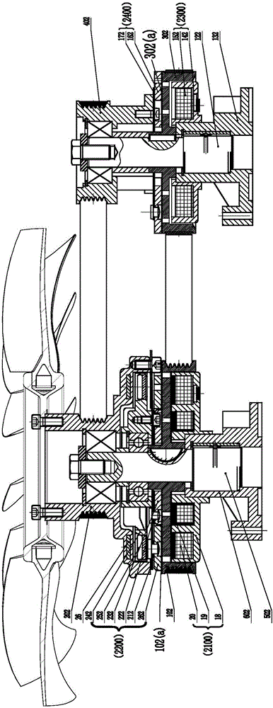
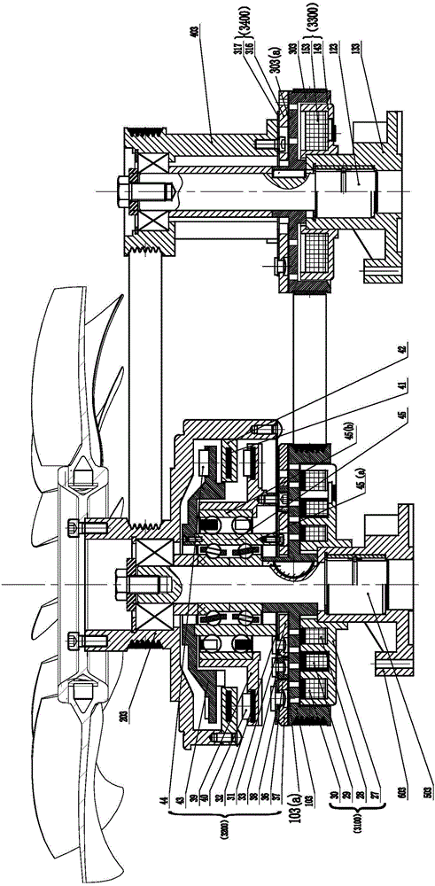
[0094] Figure 7 It is a working diagram of the second embodiment of the driving device for changing the rotation direction of the fan, the first clutch is in the engaged state, the second clutch is in the disengaged state, and the fan rotates counterclockwise.

[0095] Figure 8 It is a working schematic diagram of the second embodi...


PUM


Abstract

The invention relates to a driving device for changing a fan rotating direction and a control method. An engine transmission wheel is connected with a fan driving wheel through a fan rotating direction change device; the fan rotating direction change direction includes a first driving wheel, a second driving wheel and a driven wheel; the fan driving wheel is connected with the driven wheel through a connecting piece; the fan driving wheel is connected with the first driving wheel through a first clutch; the first driving wheel and the second driving wheel are connected with the engine transmission wheel through connecting pieces; and the driven wheel is connected with the second driving wheel through a second clutch. The driving device for changing the fan rotating direction is simple in structure, convenient to control and low in production cost, changes the fan rotating direction through changing the working states of two clutches to realize the effect of changing the air flowing direction, achieves the purposes of engine heat dissipation and self-cleaning, reduces engine faults, and prolongs the engine life.

Description

technical field [0001] The invention belongs to the technical field of road and non-road vehicle cooling systems, and in particular relates to a driving device and a control method capable of changing the rotation direction of a fan. Background technique [0002] The heat dissipation of the existing engine cooling system is mainly to drive the cooling fan directly or indirectly through the engine crankshaft to take away heat. The blade angle of the fan is a certain value, and the fan can only be used for cooling the engine. However, for heavy machinery, due to the harsh operating environment, the vehicle will produce foreign debris during the work process, which will greatly reduce the working efficiency of the radiator. If there are too many impurities, the work has to be suspended to remove the impurities in the radiator, resulting in a waste of time. Therefore, changing the direction of the fan can not only meet the cooling requirements of the engine, but also reduce th...

Claims


Application Information

Patent Timeline
Patent Type & Authority Applications(China)
IPC IPC(8): F01P5/04F01P7/08F01P7/04
CPCF01P5/04F01P7/046F01P7/081
Inventor 王兆宇刘中银刘海涛王艳立
Owner LONGKOU ZHONGYU THERMAL MANAGEMENT SYST SCIAND TECH
Why Eureka
Try Eureka