Step-by-step vane motor applicable to low speed and heavy duty

A vane motor, low-speed and heavy-duty technology, applied in the field of precision transmission, can solve problems such as complex systems and difficult problems, and achieve the effects of high precision, improved control precision, and compact structure

Active Publication Date: 2019-04-16
ZHEJIANG UNIV
View PDF9 Cites 4 Cited by
  • Summary
  • Abstract
  • Description
  • Claims
  • Application Information

AI Technical Summary

Problems solved by technology

However, the traditional hydraulic motor can only control the motion by controlling the flow of hydraulic oil, so a propor

Method used


Image

  • Step-by-step vane motor applicable to low speed and heavy duty
  • Step-by-step vane motor applicable to low speed and heavy duty
  • Step-by-step vane motor applicable to low speed and heavy duty

Examples


Example Embodiment

[0024] The present invention will be described in further detail below in conjunction with the accompanying drawings and examples.

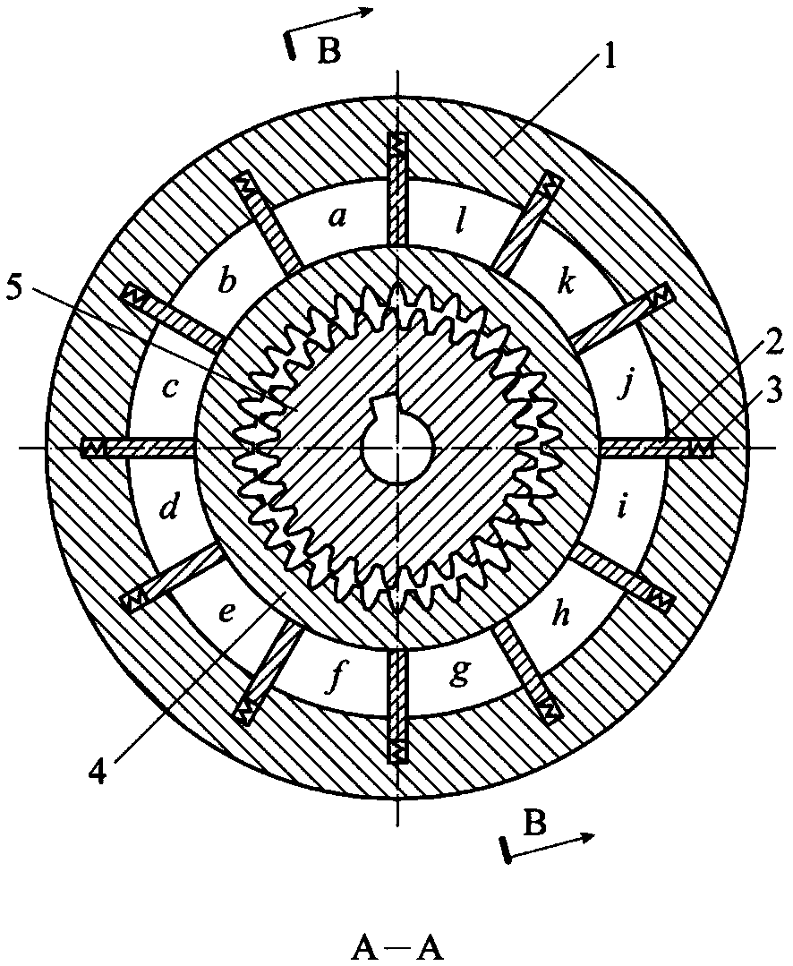
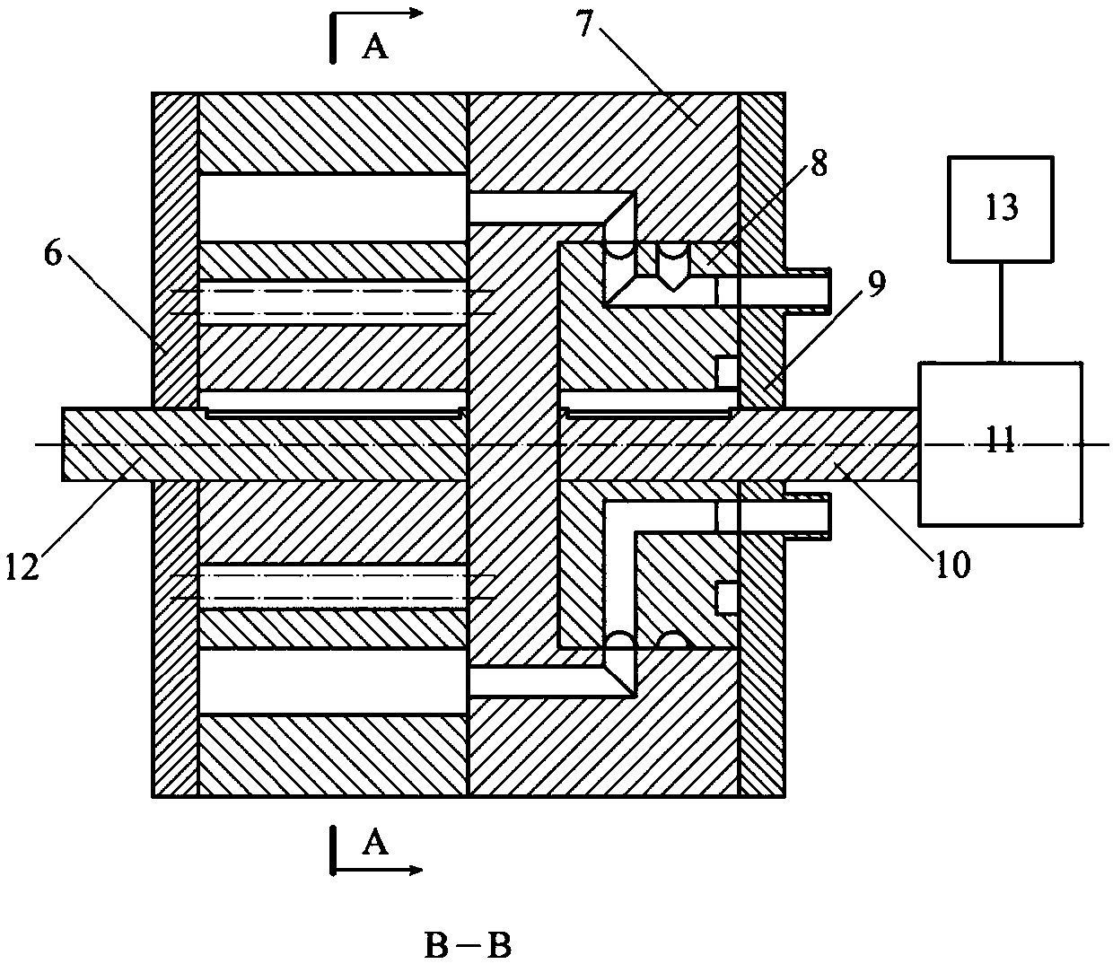
[0025] like figure 1 , figure 2 As shown, an annular outer ring 1 and a sealing disc 7 are coaxially provided between the left end cap 6 and the right end cap 9, and the left end cap 6, the annular outer ring 1, the sealing disc 7 and the right end cap 9 are sealed and connected in sequence,

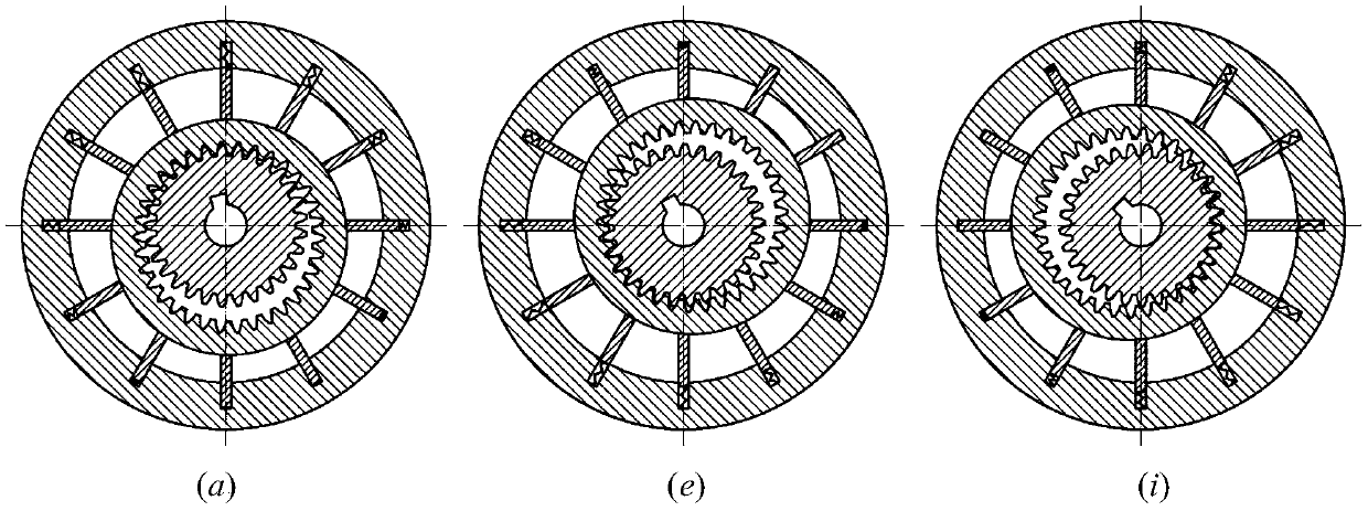
[0026] An inner gear pair is installed in the inner ring of the annular outer ring 1. The inner gear pair includes an inner gear 4 and an outer gear 5 set in the inner ring of the inner gear 4. The inner ring of the inner gear 4 is a ring gear, and the outer gear 5 is outside. The ring is a gear ring, the inner teeth of the inner gear 4 are in contact with the outer teeth of the outer gear 5, the modules of the inner gear 4 and the outer gear 5 are equal and have a difference in the number of teeth, so that the outer ring teeth of the outer gear 5 and the...


PUM


Abstract

The invention discloses a step-by-step vane motor applicable to low speed and heavy duty. A groove for a vane to embed is formed in an annular outer ring; one end of the vane is connected to the bottom part of the groove through a spring; the other end of the vane always presses against the outer edge of an inner gear through a spring action; the annular outer ring, the vane and the inner gear form multiple sealed oil cavities in a surrounding way. High-pressure oil and returned oil are introduced through an oil port in a right end cover and are led to the sealed oil cavities through an oil distribution plate and a sealed plate; the oil distribution plate is driven by a stepping motor so as to rotate, so that the high-pressure oil and the returned oil are distributed to the various sealedoil cavities; the high-pressure oil pushes the free inner gear to move so as to mesh with an outer gear fixed axially; and along with the distribution of the high-pressure oil and the returned oil, the outer gear meshes with the inner gear at different places, so that the outer gear further produces rotation, and the movement can be output through a key groove and other manners. The step-by-step vane motor applicable to low speed and heavy duty provided by the invention has the advantages of high movement accuracy, applicability to heavy-load occasions, and can be used for fine control in thefields such as robots.

Description

technical field [0001] The invention belongs to the field of precision transmission, and specifically relates to a stepping vane motor which uses hydraulic technology as a power source and a small tooth difference transmission as a transmission principle. Background technique [0002] With the continuous development of industrial technology, the requirements for automation and intelligence continue to increase, and the requirements for the action accuracy of the actuators are very strict, and the actuators are also required to have a certain bearing capacity. Various actuators based on stepper motors can easily achieve high-precision servo control, but it is difficult to apply to heavy-duty occasions. Hydraulic-driven actuators use pressure oil as a power source. Compared with motors, they have large torque, small inertia, and stable operation, and can be used in heavy-duty applications. However, in traditional hydraulic motors, motion control can only be achieved by contro...

Claims


Application Information

Patent Timeline
IPC IPC(8): F03C2/30
CPCF03C2/304
Inventor 王林翔王帆胡耀东
Owner ZHEJIANG UNIV
Why Eureka
Try Eureka