Fuel Vapor Gas Purification System

A technology of gas purification system and fuel vapor, which is applied in the direction of charging system, fuel air inlet, fuel injection device, etc., and can solve problems such as leakage of evaporated fuel

Inactive Publication Date: 2020-02-14
HAMANAKODENSO
View PDF2 Cites 0 Cited by
  • Summary
  • Abstract
  • Description
  • Claims
  • Application Information

AI Technical Summary

Problems solved by technology

[0003] According to the system of Patent Document 1, when the purge control valve is disengaged from the intake passage during the forward rotation of the purge pump, evaporated fuel may leak to the outside

Method used


Image

  • Fuel Vapor Gas Purification System
  • Fuel Vapor Gas Purification System
  • Fuel Vapor Gas Purification System

Examples


no. 1 example

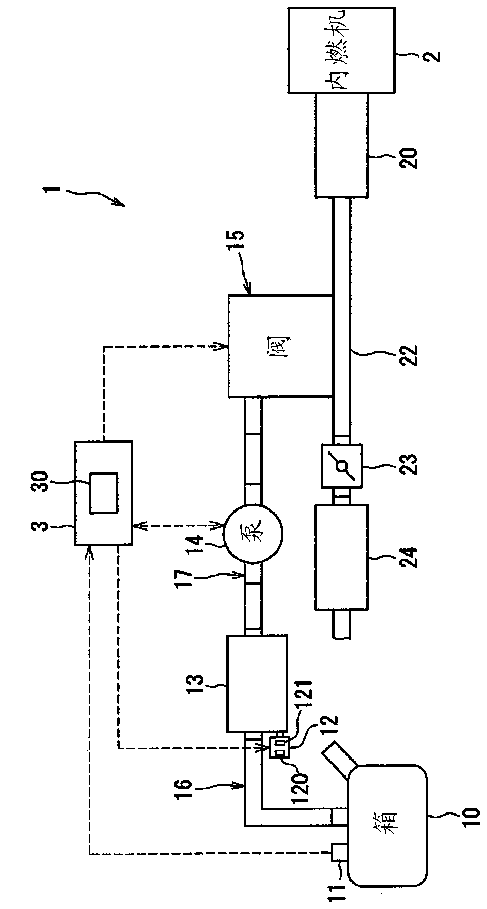
[0022] refer to Figure 1-Figure 5 , the fuel vapor gas purification system 1 according to the first embodiment will be described. The fuel vapor gas purification system 1 supplies hydrocarbon (HC) gas and the like contained in the fuel adsorbed to the canister 13 into an intake passage of the internal combustion engine. The fuel vapor gas purification system 1 prevents fuel vapor gas (hereinafter may be referred to as evaporated fuel) generated in the fuel tank 10 from being released into the atmosphere. The fuel vapor gas purification system 1 may be referred to as "system 1". Such as figure 1 As shown, the system 1 includes an intake system including an intake passage of an internal combustion engine 2 and an evaporated fuel purification system that supplies evaporated fuel to the intake system of the internal combustion engine 2 .

[0023] The evaporated fuel introduced into the intake passage of the internal combustion engine 2 is mixed with the combustion fuel supplie...

no. 2 example

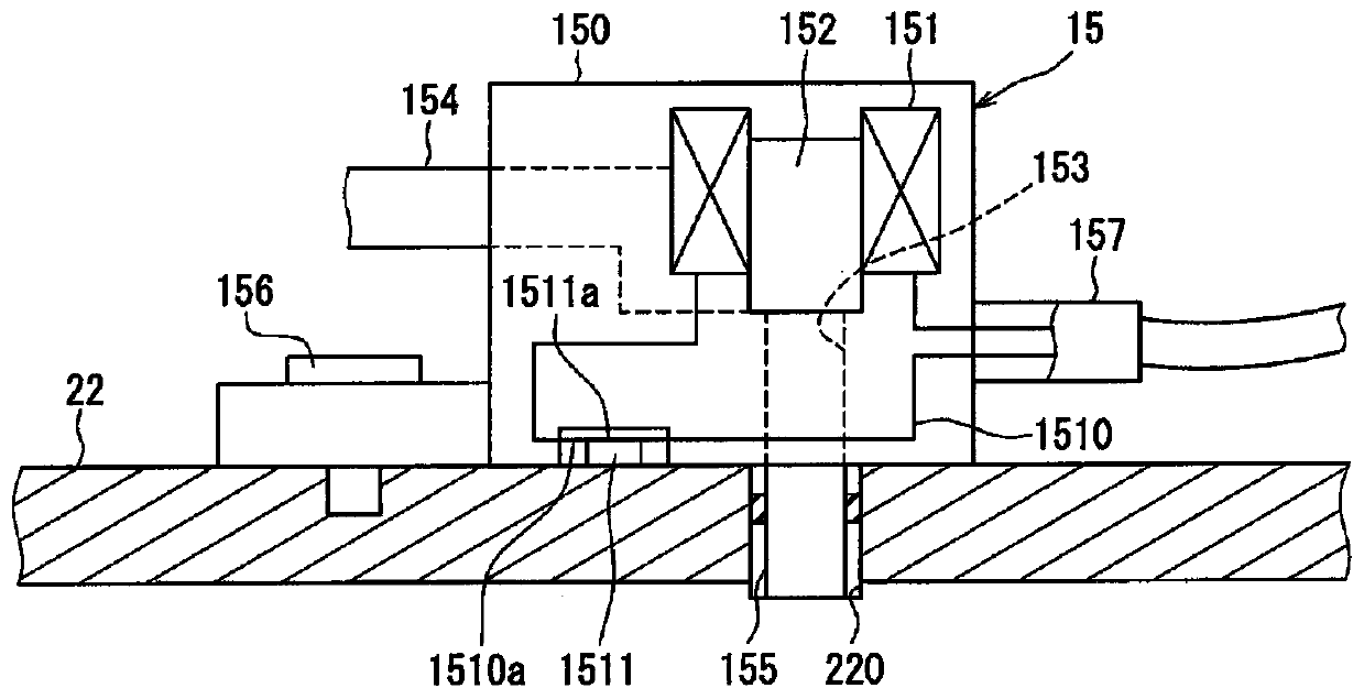
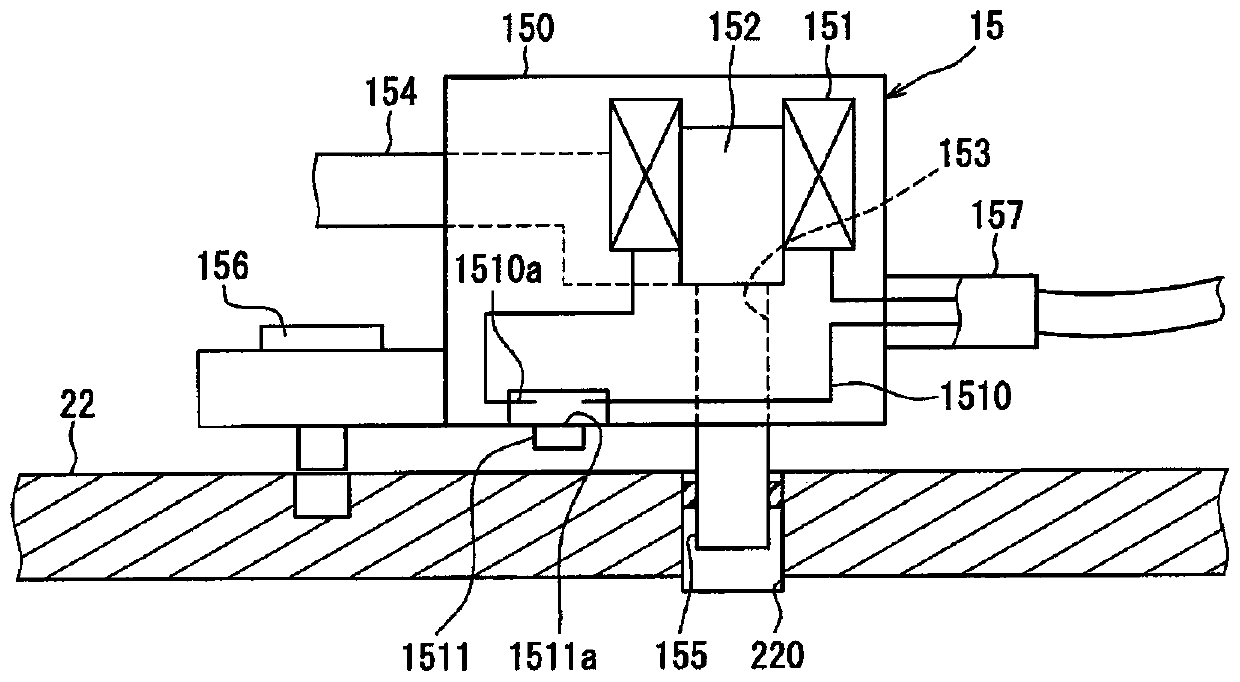
[0060] will refer to Figure 6 and Figure 7 , the fuel vapor gas purification system according to the second embodiment will be described. In each drawing, components similar to those of the first embodiment are given the same reference numerals, and have similar functions and effects. Configurations, functions and effects not specifically described in the second embodiment are similar to those of the first embodiment. Hereinafter, in the second embodiment, only points different from the above-described embodiments will be described. In the second embodiment, components including configurations similar to those of the above-described embodiment have functions and effects similar to those described in the above-described embodiment.

[0061] Such as Figure 6 As shown, the purge valve 115 as an example of the valve device differs from the first embodiment in the configuration of the switch portion 221 . The contact terminal 1510a of the circuit 1510 is connected to a swit...

no. 3 example

[0065] will refer to Figure 8 , the abnormality detection control of the fuel vapor gas purification system according to the third embodiment will be described. Configurations, functions, and effects not specifically described in the third embodiment are similar to those of the above-described embodiments. Hereinafter, in the third embodiment, only points different from the above-described embodiments will be described. In the third embodiment, components including configurations similar to those of the above-described embodiments have functions and effects similar to those described in the above-described embodiments.

[0066] The abnormality detection control described in the third embodiment is different from that of the first embodiment in that the valve device is supplied with current from the beginning, and the pump is operated during the leak check.

[0067] when Figure 8 At the beginning of the flow chart of , the controller 3 controls the purge valve 15 to be in ...


PUM


Abstract

A fuel vapor gas purification system comprising: a passage forming member (22) forming an intake passage of an internal combustion engine (2); a valve device (15) attached to the passage forming member and comprising a valve A member (152), the valve member is switchable between a permitting state allowing evaporated fuel to flow into the intake passage and a blocking state preventing the evaporated fuel from flowing into the intake passage; a circuit (1510), the The electric circuit is energized to generate a driving force to drive the valve member into a permitting state or a blocking state; a switch part (151, 221), the switch part includes an electric contact part, and the electric contact part is attached to the valve device The electrical circuit is rendered conductive when connected to the passage-forming member, and is rendered non-conductive when the valve device is disengaged from the passage-forming member.

Description

technical field [0001] The present disclosure relates to a fuel vapor gas purification system that supplies evaporated fuel from a tank into an intake pipe of an automobile. Background technique [0002] The device disclosed in Patent Document 1 (JP4082004 B2, corresponding to US2002 / 0162457A1) is considered as an example of a conventional fuel vapor gas purification system. The system of Patent Document 1 supplies fuel vapor stored in the canister through the purge passage into the intake passage of the engine by opening the purge control valve and forwardly rotating the purge pump during engine operation. [0003] According to the system of Patent Document 1, when the purge control valve is disengaged from the intake passage during forward rotation of the purge pump, evaporated fuel may leak to the outside. Contents of the invention [0004] An object of the present disclosure is to provide a fuel vapor gas purification system capable of restricting leakage of evaporate...

Claims


Application Information

Patent Timeline
Patent Type & Authority Patents(China)
IPC IPC(8): B60K15/035F02M25/08
CPCF02M25/08F02M25/0836F02M2025/0845F02M35/10222F02M25/0809F02M35/10F02D41/0037F02D41/004F02M25/089B60K15/03504B60K15/03519B01D53/0454B01D53/0407B60K2015/03514B60K2015/0319B60K2015/03243
Inventor 栃原秀哉
Owner HAMANAKODENSO
Why Eureka
Try Eureka