Intermittent drive non-abrasion hard sealed butterfly valve

A hard-sealing, non-wearing technology, applied in shaft seals, lift valves, valve details, etc., can solve the problems of complex manufacturing process and assembly process, uneven specific pressure of the sealing surface, reduced valve stem strength, etc., and achieve installation accuracy. Low requirements, various drive modes, and improved sealing performance

Active Publication Date: 2017-05-17
HEBEI UNIV OF TECH
View PDF4 Cites 4 Cited by
  • Summary
  • Abstract
  • Description
  • Claims
  • Application Information

AI Technical Summary

Problems solved by technology

Although this kind of butterfly valve reduces the wear and tear, it still has the following disadvantages: 1. There are curved grooves and long keyways on the valve stem, which greatly reduces the strength of the valve stem; 2. The structure is complicated, and the manufacturing process and assembly process are complicated. High cost; 3. The valve stem needs to move upward first, then rotate, and the operation is complicated; 4. The drive mode is single, and it is difficult to realize electric drive; 5. The specific pressure of the sealing surface is not uniform enough

Method used


Image

  • Intermittent drive non-abrasion hard sealed butterfly valve
  • Intermittent drive non-abrasion hard sealed butterfly valve
  • Intermittent drive non-abrasion hard sealed butterfly valve

Examples


Embodiment Construction

[0025] Further describe the present invention below in conjunction with embodiment and accompanying drawing thereof, but it does not limit the protection scope of the claims of the present invention.

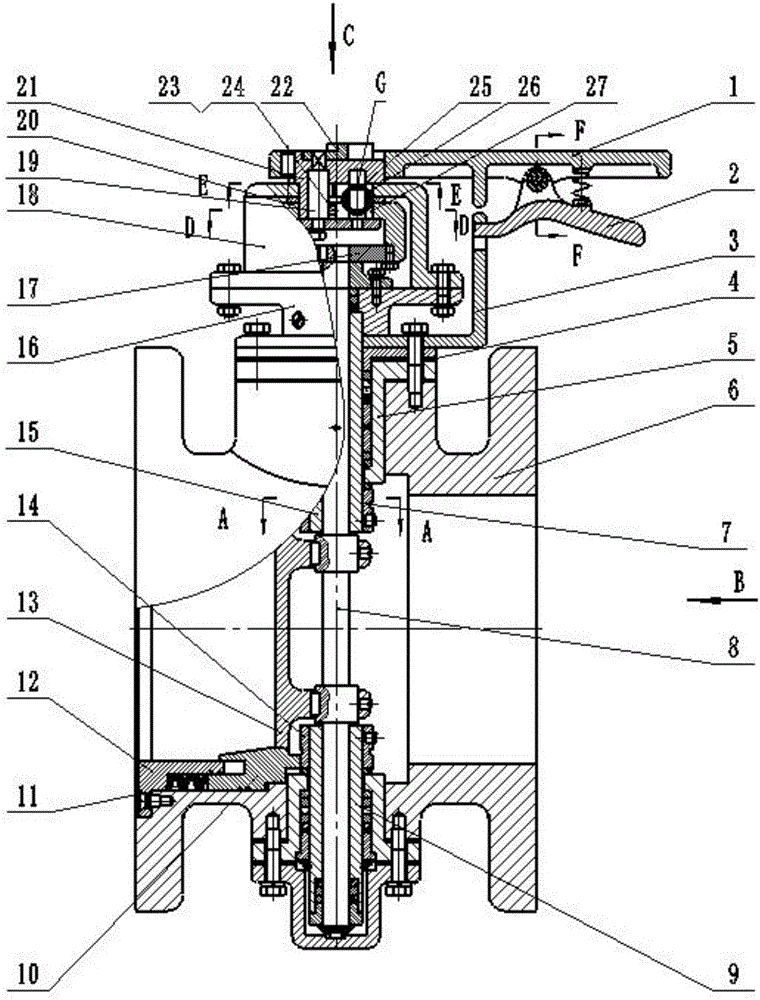
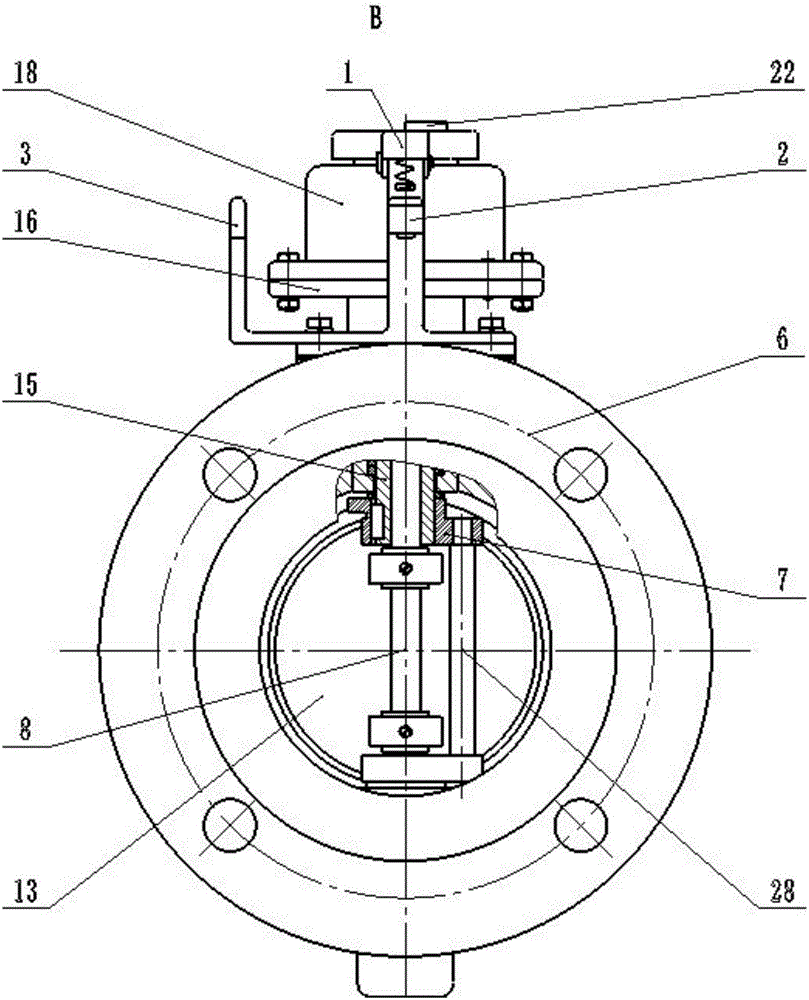
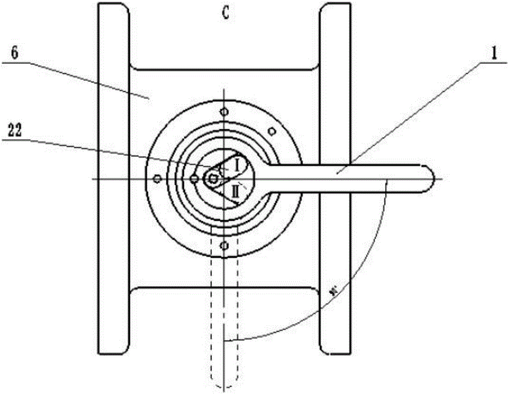
[0026] An intermittently driven wear-free hard-sealed butterfly valve designed by the present invention (hereinafter referred to as butterfly valve, see figure 1 ), the butterfly valve includes a valve body 6, a movable valve seat 10, a valve stem 8, a lower valve stem cover 9, an upper valve stem cover 15, a butterfly plate 13 and an intermittent drive device; The flange of the body 6 axis is used for the connection between the butterfly valve and the pipeline flange, and the upper and lower ends of the valve body 6 are provided with an upper valve stem sleeve hole and a lower valve stem sleeve hole, and the overall valve body 6 is cast process, the design and manufacturing process is simple, the processing is convenient, and the cost is reduced. The actual production is relati...


PUM


Abstract

The invention discloses an intermittent drive non-abrasion hard sealed butterfly valve. The intermittent drive non-abrasion hard sealed butterfly valve is characterized in that the butterfly valve comprises a valve body, a movable valve seat, a valve rod, a lower valve rod sleeve, an upper valve rod sleeve, a butterfly plate and an intermittent driving device; the left side and the right side of the valve body are provided with flanges perpendicular to the axis of the valve body; the flanges are used for connecting the butterfly valve with a pipeline flange; the upper end and the lower end of the valve body are provided with an upper valve rod sleeve hole and a lower valve rod sleeve hole; a cavity of the valve body is a stepped hole; the upper valve rod sleeve and the lower valve rod sleeve penetrate into the valve body through the upper valve rod sleeve hole and the lower valve rod sleeve hole correspondingly; retainer cups are arranged between the upper valve rod sleeve and the valve body as well as between the lower valve rod sleeve and the valve body; the retainer cups are connected with the valve body through bolts, and adjusting gaskets are installed between the retainer cups and the valve body; both the upper end and the lower end of the same busbar of the upper valve rod sleeve are provided with flat key grooves, in addition, an upper cam is fixedly installed at the lower end of the upper valve rod sleeve through a flat key, and the upper end of the upper valve rod sleeve is connected with the intermittent driving device; the upper end of the lower valve rod sleeve is provided with a flat key groove, and a lower cam is fixedly installed at the upper end of the lower valve rod sleeve through a flat key; and a transferring shaft is installed between the upper cam and the lower cam.

Description

technical field [0001] The invention relates to the technical field of butterfly valves, in particular to an intermittently driven wear-free hard-sealed butterfly valve. Background technique [0002] Due to the good sealing performance and simple structure of ordinary butterfly valves, they are widely used in general industries such as chemical industry, city gas, and water treatment. However, due to its structural characteristics and sealing characteristics, when the butterfly valve is opened and closed, there is a large friction between the sealing pairs, and the deformation of the seal is also large, which increases the torque of the opening and closing valve and slows down the opening and closing speed. . Due to the different degrees of wear of the sealing pairs, the sealing specific pressure between the sealing pairs is not fixed, which affects the sealing stability of the butterfly valve. Frequent opening and closing of the butterfly valve is likely to cause wear on ...

Claims


Application Information

Patent Timeline
Patent Type & Authority Applications(China)
IPC IPC(8): F16K1/22F16K1/42F16K1/226F16K1/36F16K1/32F16K31/53F16K41/02
CPCF16K1/221F16K1/222F16K1/226F16K1/2268F16K1/32F16K1/42F16K31/53
Inventor 戴士杰齐超群周国霞张建辉张慧博
Owner HEBEI UNIV OF TECH
Why Eureka
Try Eureka