
Low-temperature fire extinguisher valve structure

A technology for fire extinguishers and valves, which is applied in the direction of lifting valves, valve details, valve devices, etc., can solve problems such as leakage of fire extinguisher valves, and achieve the effect of good sealing reliability and convenient use

Active Publication Date: 2017-05-17
ZHEJIANG ORIENTX FIRE SAFETY EQUIP
View PDF5 Cites 12 Cited by
  • Summary
  • Abstract
  • Description
  • Claims
  • Application Information

AI Technical Summary

Problems solved by technology

The current low-temperature fire extinguisher valve will leak when used in a low-temperature environment below -20 degrees Celsius

Method used


Image

  • Low-temperature fire extinguisher valve structure
  • Low-temperature fire extinguisher valve structure
  • Low-temperature fire extinguisher valve structure

Examples


Embodiment 1

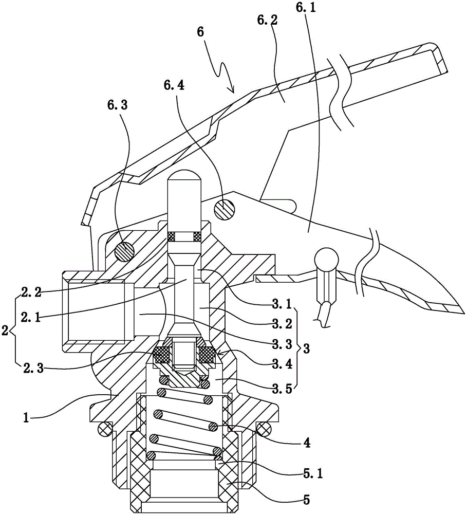
[0031] Example 1: Such as figure 1 As shown, a low-temperature fire extinguisher valve structure includes a valve body 1; a valve body flow passage 3 arranged in the valve body; a valve core 2 used to control the on-off of the valve body flow passage; a riser sleeve 5; The first return spring 4 and the fire extinguisher handle 6.

[0032] The valve body flow passage includes a main flow passage penetrating the upper and lower ends of the valve body, and a valve body outlet 3.3 which is arranged on the side surface of the valve body and communicates with the main flow passage. The lower port of the main flow channel constitutes the inlet of the valve body. The main flow path includes an upper valve hole 3.1, a middle valve hole 3.2 located below the upper valve hole, a tapered valve hole 3.4 whose inner diameter gradually decreases from bottom to top, and a lower valve hole 3.5 located below the middle valve hole. The inner diameter of the middle valve hole is larger than the inn...

Embodiment 2

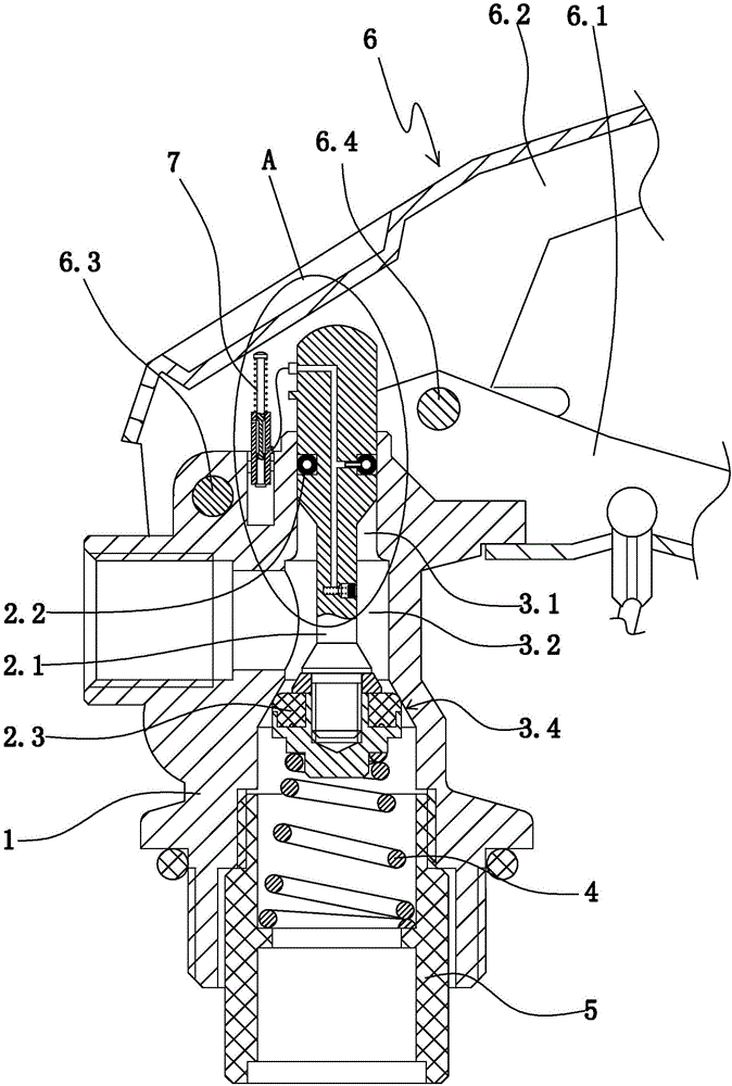
[0044] Embodiment 2: The rest of the structure of this embodiment refers to Embodiment 1, and the difference lies in:

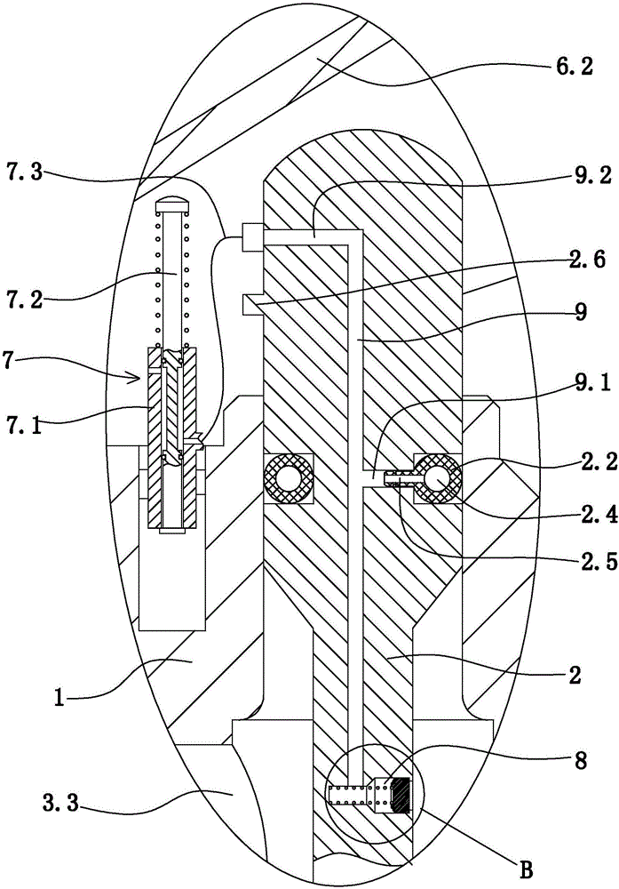
[0045] Such as figure 2 , image 3 As shown, a low-temperature fire extinguisher valve structure further includes an adaptive charging and discharging sealing structure. An installation groove for the sealing ring on the valve stem is provided on the outer surface of the valve stem. The upper sealing ring of the valve stem is arranged in the mounting groove of the upper sealing ring of the valve stem. An annular gas filled cavity 2.4 is provided in the sealing ring on the valve stem. The outer surface of the sealing ring on the valve stem is also provided with an inflatable cannula 2.5 communicating with the annular inflatable cavity.

[0046] The self-adaptive charging and discharging sealing structure includes an self-adaptive on-off mechanism 7, a pressure-type inflatable structure 8, and a main channel 9 in the valve stem.

[0047] Such as image 3 , Figure...


PUM


Abstract

The invention discloses a low-temperature fire extinguisher valve structure, and aims at providing a low-temperature fire extinguisher valve structure which is convenient to use, good in sealing reliability and capable of effectively solving the problem that leakage will occur to an existing low-temperature fire extinguisher valve when the fire extinguisher valve is used in a low-temperature environment. The low-temperature fire extinguisher valve structure comprises a valve body, a valve body flow channel arranged in the valve body and a valve element. The valve body flow channel comprises a main flow penetrating through the upper end and the lower end of the valve body and a valve body outlet formed in the outer side face of the valve body and communicating with the main flow channel, a lower port of the main flow channel forms a valve inlet, and the main flow channel comprises a conical valve hole with the inner diameter gradually reduced from the bottom to the top. The valve element is used for controlling the valve body flow channel to be opened and closed. The valve element comprises a valve rod, a valve rod upper sealing ring and a valve rod lower sealing ring, wherein the valve rod is inserted into the main flow channel, the valve rod upper sealing ring is arranged on the valve rod and in sealed connection with the main flow channel, and the valve rod lower sealing ring is arranged on the valve rod and in sealed connection with the conical valve hole. The valve body outlet is located between the valve rod upper sealing ring and the valve rod lower sealing ring.

Description

Technical field [0001] The invention relates to a valve structure, in particular to a low-temperature fire extinguisher valve structure. Background technique [0002] Low temperature fire extinguishers are generally used in northern areas where the temperature is lower than -20 degrees Celsius for a long time. The current low temperature fire extinguisher valves usually consist of a valve body, a valve stem, a pressing handle and a handle. The valve stem is installed in the valve body, and the valve stem is equipped with a valve. The body cooperates to form a sealing ring of the sealing structure. The current low temperature fire extinguisher valve used in a low temperature environment below -20 degrees Celsius will cause the fire extinguisher valve to leak. Summary of the invention [0003] The purpose of the present invention is to overcome the deficiencies in the prior art, provide a low temperature fire extinguisher valve that is convenient to use, has good sealing reliabilit...

Claims


Application Information

Patent Timeline
IPC IPC(8): F16K41/02F16K1/00F16K1/36
CPCF16K1/00F16K1/36F16K41/02
Inventor 陈巅杨俊王锡均
Owner ZHEJIANG ORIENTX FIRE SAFETY EQUIP
Features
  • Generate Ideas
  • Intellectual Property
  • Life Sciences
  • Materials
  • Tech Scout
  • Unparalleled Data Quality
  • Higher Quality Content
  • 60% Fewer Hallucinations
Learn More