A rotating solar bracket

A solar energy and rotary technology, applied in the field of solar support, can solve the problems of high cost, complex structure of solar support, poor strength and stability, etc., and achieve the effect of low cost, effective and reliable support, and good stability

Active Publication Date: 2019-04-05
YUEQING YIHUA NEW ENERGY TECHNOLOGY CO LTD
View PDF4 Cites 0 Cited by
  • Summary
  • Abstract
  • Description
  • Claims
  • Application Information

AI Technical Summary

Problems solved by technology

[0004] Therefore, the technical problem to be solved by the present invention is to overcome the defects of complex structure, high cost and poor strength stability of the solar support in the prior art, so as to provide a rotary support that is simple in structure, stable and firm, and can adapt to harsh environments. type solar bracket

Method used


Image

  • A rotating solar bracket
  • A rotating solar bracket
  • A rotating solar bracket

Examples


Embodiment

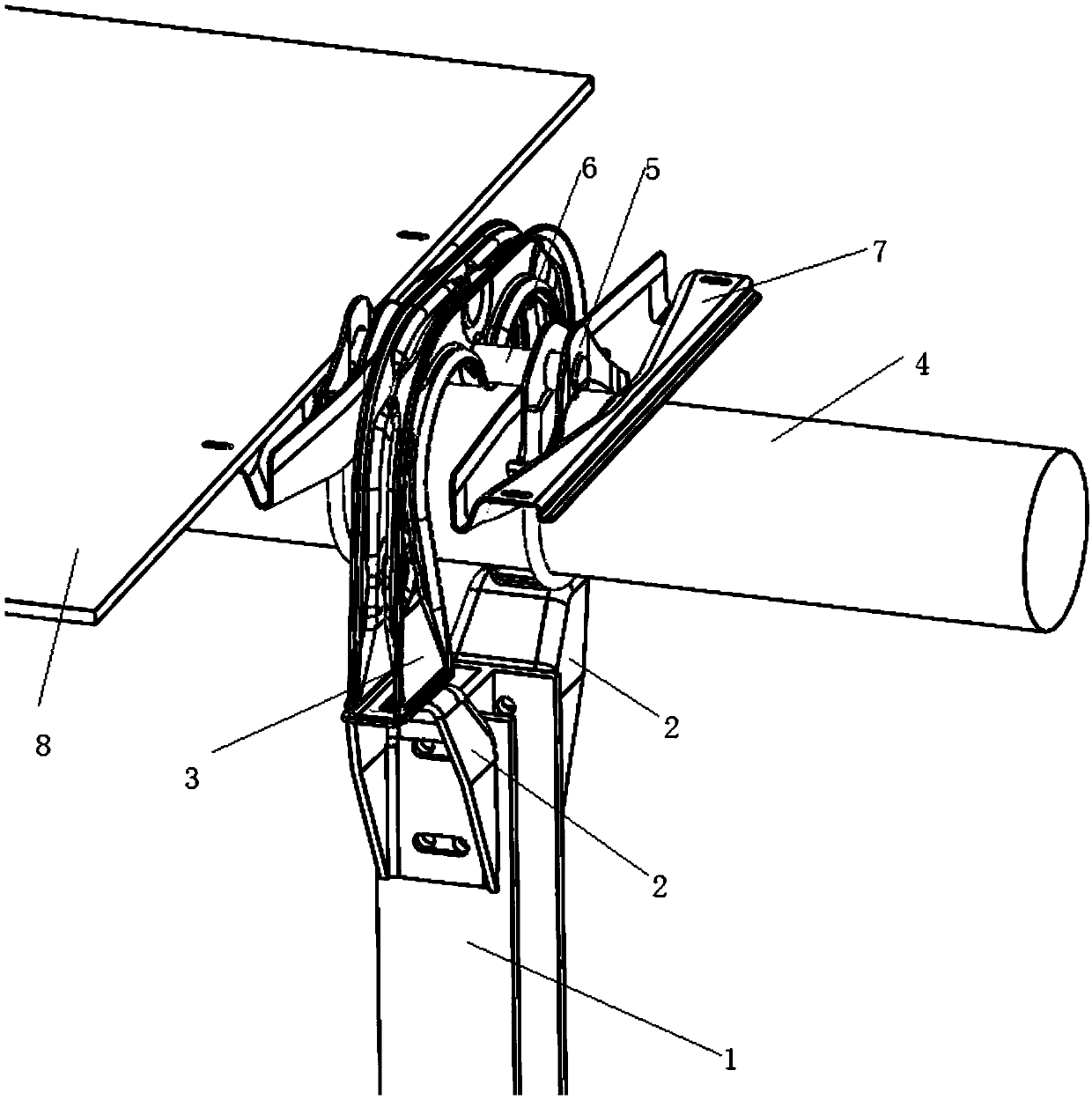
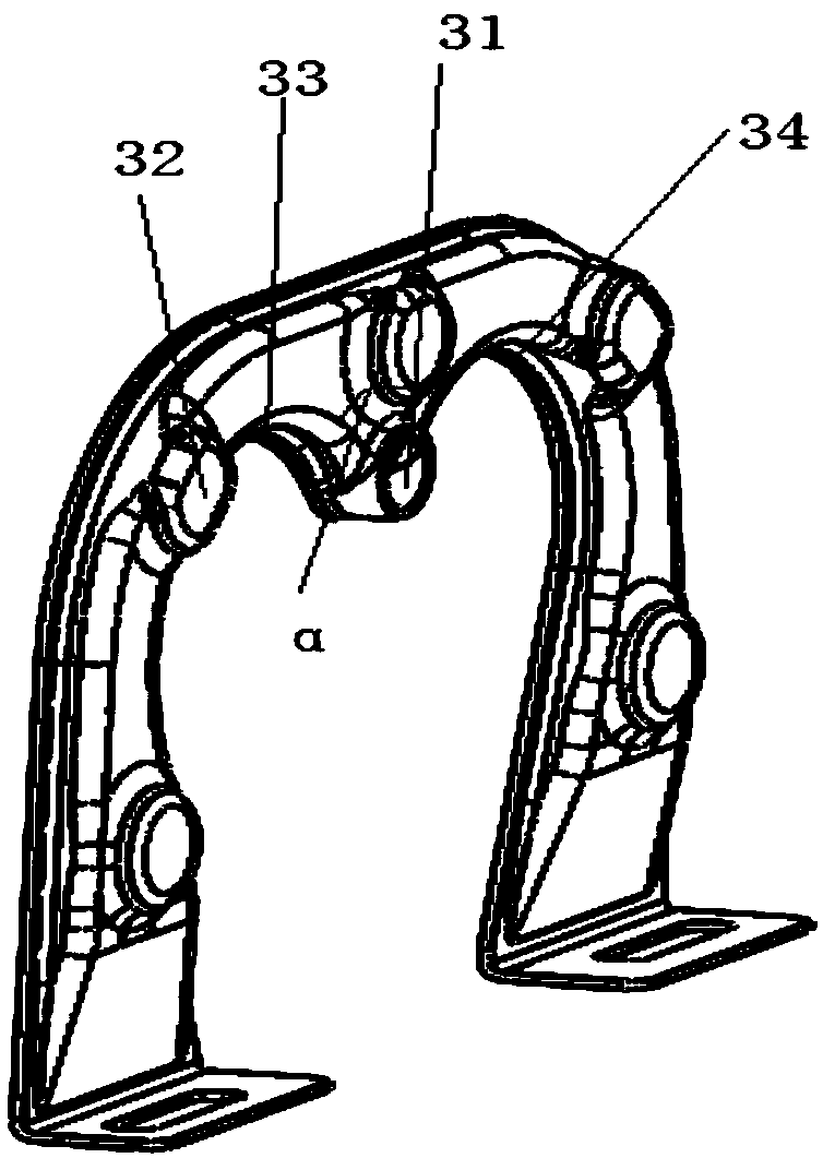
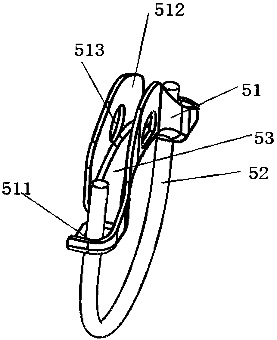
[0034] A rotating solar bracket such as figure 1As shown, it includes a column 1 fixedly connected to the ground at one end, a fixing piece 2 is installed on the opposite side of the other end of the column 1, and a support frame 3 is connected to the upper ends of the two fixing pieces 2, and the support frame 3 is connected to the two sides. A cavity is formed between the two fixing parts 2, and the rotating shaft 4 used to drive the solar panel 8 to rotate passes through the cavity and is held and fixed by the fastening structure 5, and the fastening structure 5 passes through the connecting piece. 6 is rotatably connected to the support frame 3, and a mounting part 7 for installing the solar panel 8 and capable of rotating with the rotating shaft 4 is arranged between the fastening structure 5 and the rotating shaft 4. The rotating shaft 4 is energized and rotated, and the fastening structure 5 and the mounting part 7 connected thereto are rotated accordingly, thereby driv...


PUM


Abstract

The invention discloses a rotating type solar support which comprises a stand column. One end of the stand column is fixedly connected with the ground, and fixing parts are oppositely installed on the two sides of the other end of the stand column. A supporting frame is connected with the upper ends of the two fixing frames. A cavity is formed among the supporting frame and the two fixing parts. A rotating shaft used for driving a solar panel to rotate penetrates the cavity and is firmly hooped and fixed through a fastening structure. The fastening structure is rotationally connected with the supporting frame through a connecting piece. An installation part used for installing the solar panel and can rotate along with the rotating shaft is arranged between the fastening structure and the rotating shaft. When the rotating shaft is electrified to rotate, the fastening structure and the installation part which are connected with the rotating shaft rotate along with the rotating shaft, and therefore the solar panel is driven to move. The above solar support is simple in structure, firm, reliable and capable of working normally under the severe conditions.

Description

technical field [0001] The invention relates to the technical field of solar support, in particular to a rotary solar support. Background technique [0002] With the progress and development of society, clean energy is more and more popular among people. As a clean and renewable energy, solar power is gradually entering people's field of vision. Solar power generation is to gather sunlight in a certain area on a narrow solar panel, and generate electricity through photoelectric conversion, which requires that the sunlight can be vertically incident on the solar panel, so that the solar bracket that can track the incident light of the sun came into being. [0003] At present, most of the solar brackets on the market that can track the incident light of the sun use more complex components such as support beams and mounting frames to support the solar panel, and then use the rotating structure to drive the components installed with the solar panel to rotate together, not only m...

Claims


Application Information

Patent Timeline
Patent Type & Authority Patents(China)
IPC IPC(8): F24S30/425H02S20/30
CPCF24S30/425H02S20/30Y02E10/47Y02E10/50
Inventor 黄泽斌季开良郑向如
Owner YUEQING YIHUA NEW ENERGY TECHNOLOGY CO LTD
Why Eureka
Try Eureka