Acoustic array imaging system and method thereof

An imaging system and array technology, used in radio wave measurement systems, sound wave re-radiation, and utilization of re-radiation, etc., can solve the problems of occupying a large storage space, not suitable for real-time imaging, and time-consuming for calculation, and the calculation is time-consuming. Small, improve the operation speed, the effect of less storage space

Active Publication Date: 2017-05-17
INST OF ACOUSTICS CHINESE ACAD OF SCI
View PDF5 Cites 12 Cited by
  • Summary
  • Abstract
  • Description
  • Claims
  • Application Information

AI Technical Summary

Problems solved by technology

[0005] The purpose of the present invention is to solve the problem in the prior art that in the all-focus imaging method, each receiving process is a full-aperture data collection, wh

Method used


Image

  • Acoustic array imaging system and method thereof
  • Acoustic array imaging system and method thereof
  • Acoustic array imaging system and method thereof

Examples


Embodiment Construction

[0047] The technical solutions of the present invention will be described in further detail below with reference to the accompanying drawings and embodiments.

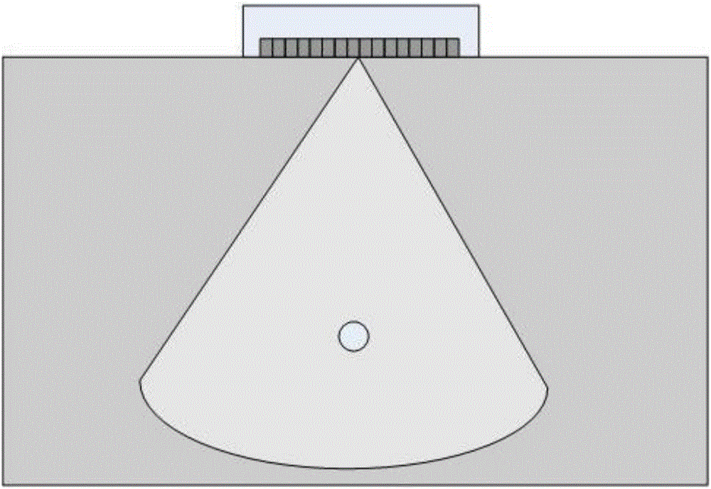
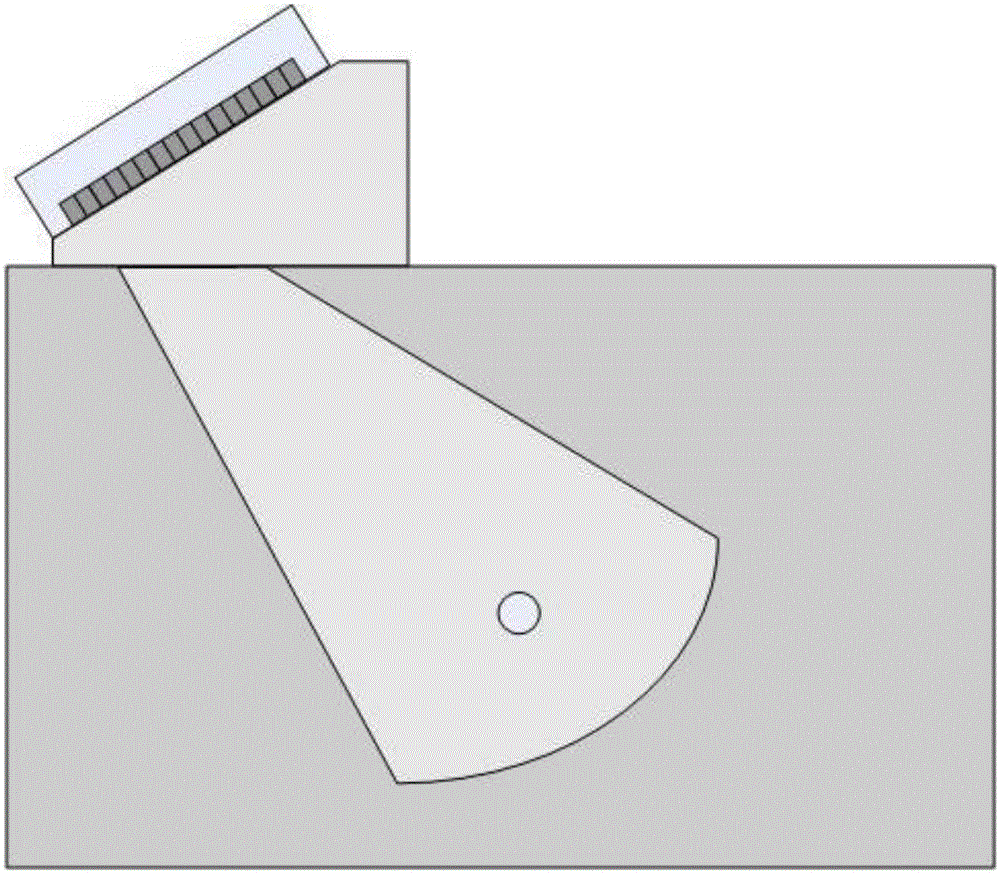
[0048] Figure 1 shows the schematic diagrams of direct contact sector scanning and shear wave S-shape scanning generated by wedges, respectively.

[0049] Fig. 1(a) is a schematic diagram of an ultrasonic array longitudinal wave scanning imaging detection. As shown in Figure 1, the electronic system changes the angle of the incident longitudinal wave by controlling the delay of different array elements to achieve the purpose of imaging the fan-shaped area. This method is called B-mode imaging.

[0050] Fig. 1(b) is a schematic diagram of an ultrasonic array shear wave scanning imaging detection provided by an embodiment of the present invention. As shown in Figure 1(b), the electronic system controls the delay of different array elements, and makes the incident longitudinal wave obliquely incident on the part along th...


PUM


Abstract

The method relates to an acoustic array imaging system and a method thereof. The system comprises a data acquisition module 101, a first imaging module 102, a second imaging module 103 and an image composite module 104. The method comprises the following steps of successively emitting array elements in an acoustic array and collecting echo signals so as to acquire an analysis signal; according to a sound propagation relation between the emitted array elements and receiving array elements in an array, acquiring a time-delay value, and according to the analysis signal and the time-delay value, calculating images of the receiving array elements; using a cascaded parallel composite processing unit to recombine the image of all the receiving array elements; and superposing all the composite images and carrying out envelope processing so as to acquire a full-matrix data acquisition imaging result. The system and the method have advantages that when each array element data is collected, processing is performed so that an occupied storage space is small; a parallel mode is used to increase an operation speed; during an actual application, calculating time consuming is less, and high frame rate imaging can be realized; and the method and the system are suitable for real-time data processing and high resolution imaging. In addition, the system and the method are suitable for acoustic array imaging under different frequency and application scenes.

Description

technical field [0001] The invention relates to the technical field of acoustic array imaging, in particular to a distributed parallel full-matrix acoustic array imaging system and method. Background technique [0002] At present, acoustic array imaging is of great significance to industries such as industrial non-destructive testing, medicine and underwater testing, and has been widely used in recent years. [0003] Ultrasonic array testing technology is based on ultrasonic array transducers, using ultrasonic longitudinal waves or transverse waves, a method for non-destructive testing of industrial parts. Ultrasonic array detection technology can also be used to detect complex materials such as composite materials. This method has great flexibility and can detect parts with irregular shapes. Compared with the traditional single-array element flaw detection method, it has the advantages of large detection area, high signal-to-noise ratio, and intuitive detection results. ...

Claims


Application Information

Patent Timeline
IPC IPC(8): G01S15/89G01S7/52G01S7/539
CPCG01S7/52017G01S7/539G01S15/8906
Inventor 吴文焘张云翼曹政韩晓丽
Owner INST OF ACOUSTICS CHINESE ACAD OF SCI
Why Eureka
Try Eureka