
Seismic source positioning method based on P-wave arrival time and waveform amplitude

A technology of waveform amplitude and seismic source positioning, which is applied in seismology, seismic signal processing, measuring devices, etc., can solve the problems of positioning accuracy and precision randomness, automatic and accurate picking, etc., achieve high accuracy, improve positioning accuracy and Accuracy, clear results

Active Publication Date: 2017-05-17
CENT SOUTH UNIV
View PDF4 Cites 9 Cited by
  • Summary
  • Abstract
  • Description
  • Claims
  • Application Information

AI Technical Summary

Problems solved by technology

Moreover, there are still problems in the automatic and accurate picking of the S wave arrival time, which needs to be picked up manually by experienced professional staff, and there is a large randomness in the positioning accuracy and precision
[0004] It can be seen that the existing methods for localizing the source of microseismic and blasting events have great limitations, and it is necessary to study a localization method with strong applicability and high accuracy

Method used


Image

  • Seismic source positioning method based on P-wave arrival time and waveform amplitude
  • Seismic source positioning method based on P-wave arrival time and waveform amplitude
  • Seismic source positioning method based on P-wave arrival time and waveform amplitude

Examples


Embodiment

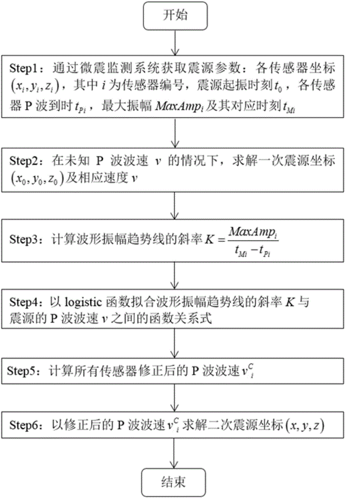
[0064] From step 2, the focal coordinates of one localization can be obtained as follows:

[0065] Table 1 The actual coordinates and primary positioning coordinates of the five groups of seismic sources

[0066]

[0067]

[0068] From Step 3, Step 4, and Step 5, Table 2 can be obtained as follows:

[0069] Table 2 K-v function relational expression of 5 groups of seismic sources

[0070]

[0071]

[0072] From step 6, the coordinates of the secondary seismic source can be obtained as shown in the table below

[0073] Table 3 The actual coordinates and secondary positioning coordinates of the five groups of seismic sources

[0074]

[0075] It can be seen from Table 3 that after speed correction, the accuracy of the secondary positioning coordinates is significantly higher than that of the primary positioning coordinates.


PUM


Abstract

The invention discloses a seismic source positioning method based on P-wave arrival time and waveform amplitude. The method comprises following steps of step 1, acquiring seismic source parameters through a micro-seismic monitoring system; step 2, in case of unknown P-wave wave speed v, solving a primary seismic source coordinate (x0, y0, z0) and corresponding speed v; step 3, calculating the slope K of a waveform amplitude trend line, wherein K is defined in the description; step 4, using the logistic function to fit the function relation expression between the slope K of the waveform amplitude trend line and the P-wave wave speed v of each seismic source; step 5, calculating the P-wave wave speed v<c> of each corrected sensor; and step 6, using the P-wave wave speed v<c> of each corrected sensor to solve a secondary seismic source coordinate (x, y, z). The method is characterized by high adaptability and precision.

Description

technical field [0001] The invention relates to a seismic source location method based on P wave arrival time and waveform amplitude, which has clear results, strong applicability and high accuracy. Background technique [0002] As one of the important technical means of underground engineering safety monitoring, microseismic monitoring has been widely used in mine safety, hydropower engineering and other fields. The determination of the spatial location of the microseismic source and the improvement of the positioning accuracy of the microseismic source have always been important contents of the microseismic monitoring technology. However, the waveforms of microseismic and blasting events are relatively complex, and the first wave of the S wave is usually mixed with the coda wave of the P wave, which makes it difficult to identify the S wave when it arrives, and is easily affected by the professional knowledge and experience of the operator, which greatly reduces the The a...

Claims


Application Information

Patent Timeline
IPC IPC(8): G01V1/30
CPCG01V1/30G01V2210/65
Inventor 董陇军舒炜炜李夕兵
Owner CENT SOUTH UNIV
Learn More