
State management method, system and device for safety tool

A safety tool and state management technology, applied in the field of safety tool state management, can solve problems such as the storage of safety tools in an environment that does not meet the requirements, the inability to detect the test time for inspection in time, and the long working hours of cable shifts. To achieve the effect of strong pertinence, easy processing and cost-effective reminder

Pending Publication Date: 2017-05-17
HONGHE POWER SUPPLY BUREAU OF YUNNAN POWER GRID
View PDF7 Cites 2 Cited by
  • Summary
  • Abstract
  • Description
  • Claims
  • Application Information

AI Technical Summary

Problems solved by technology

However, in actual work, the cable shift goes out to work for a long time. It is usually late at night when the work ends, or the ring network cabinet is operated at night, which is inconvenient for inspection and storage. The tools and appliances have not been put into storage and are used by other people, resulting in the frequent use of some of the same kind of tools and appliances, while the utilization rate of the rest is low, and the use is unreasonable
At the same time, there may be situations where the tool cannot be checked and put into storage in time after use, and the tool is forgotten the next day.
This will cause the problem of long-term storage of safety equipment in an environment that does not meet the requirements.
[0006] At the same time, insulation safety tools need to be tested regularly, and different tools have different test cycles.
In order to prevent the uninspection of tools and appliances beyond the time limit, the existing methods are all through manual inspection and paper records. In this way, it may not be found in time that the test time is about to expire and needs to be sent for inspection

Method used


Image

  • State management method, system and device for safety tool
  • State management method, system and device for safety tool
  • State management method, system and device for safety tool

Examples


Embodiment Construction

[0050] In order to make the above objects, features and advantages of the present invention more comprehensible, the present invention will be further described in detail below in conjunction with the accompanying drawings and specific embodiments.

[0051]Reference herein to "one embodiment" or "an embodiment" refers to a particular feature, structure or characteristic that can be included in at least one implementation of the present invention. "In one embodiment" appearing in different places in this specification does not all refer to the same embodiment, nor is it a separate or selective embodiment that is mutually exclusive with other embodiments.

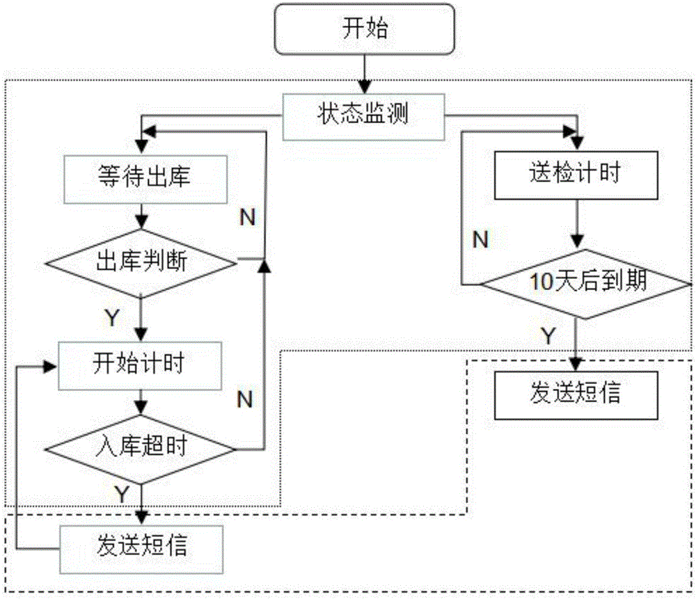
[0052] see figure 1 , figure 1 It is a flow chart of the method for managing the state of the safety appliance of the present invention. like figure 1 As shown, the present invention provides a method for managing the state of safety tools and appliances, which monitors the status of the tools and appliances to be delivere...


PUM


Abstract

The invention provides a state management method, system and device for a safety tool. The method includes: monitoring the to-be-discharged state and to-be-inspected state of the tool, to be more specific, judging whether the tool is discharged out of storage or not; if so, performing tool storing count down, and if not, continuously monitoring the to-be-discharged state of the tool; if tool storing overtime occurs, sending a text message to the mobile equipment of storing overtime staff and continuing the count down at the same time, and if tool storing overtime does not occur, continuously monitoring the to-be-discharged state of the tool. By the method, the timely storing rate of the safety tool discharged out of storage can be increased from 33% to 100%.

Description

technical field [0001] The invention relates to the field of safety tools, in particular to a method, system and device for state management of safety tools. Background technique [0002] Basic insulation safety tools refer to tools that can directly operate live equipment or contact or may touch live bodies, such as capacitive electroscopes, insulating rods, nuclear phase detectors, insulating covers, insulating partitions, etc. The difference between operating tools is that they are short-term contact with electrified bodies or non-contact electrified bodies during work. Auxiliary insulation safety equipment means that the insulation strength does not withstand the working voltage of equipment or lines, but is only used to strengthen the security function of basic insulation safety equipment to prevent contact voltage, step voltage, and leakage current arc from harming operators. Do not directly contact live parts of high-voltage equipment with auxiliary insulation safety...

Claims


Application Information

Patent Timeline
Patent Type & Authority Applications(China)
IPC IPC(8): G06Q10/08
CPCG06Q10/087
Inventor 董昊刘刚韦明黄泽龙赵宝白汶龙张荣琨任锐李锦荣钱朝武段志云
Owner HONGHE POWER SUPPLY BUREAU OF YUNNAN POWER GRID
Learn More