
Winding machine for frameworks of transformers

A technology of transformer skeleton and winding machine, which is used in inductor/transformer/magnet manufacturing, coil manufacturing, electrical components, etc., can solve the problems of labor-intensive labor, uneven distribution, rework, etc., to avoid winding and knotting, and ensure efficiency. , the effect of improving efficiency

Active Publication Date: 2017-05-17
威海合益电子科技有限公司
View PDF7 Cites 3 Cited by
  • Summary
  • Abstract
  • Description
  • Claims
  • Application Information

AI Technical Summary

Problems solved by technology

[0003] Most of the existing winding equipment for transformer skeletons fix the transformer on the turntable, and the winding of the transformer is realized through the rotation of the turntable. When winding, it is necessary to stop the machine frequently to adjust the position of the winding, so that the copper wire is relatively uniform. Winding on the transformer skeleton, using this method for winding, consumes a lot of manpower, and the effect of winding is not very good, prone to uneven distribution and lead to rework, and copper wire winding may also occur The case of knotting

Method used


Image

  • Winding machine for frameworks of transformers
  • Winding machine for frameworks of transformers
  • Winding machine for frameworks of transformers

Examples


Embodiment Construction

[0035] In order to enable those skilled in the art to better understand the technical solution of the present invention, the present invention will be described in detail below in conjunction with the accompanying drawings. The description in this part is only exemplary and explanatory, and should not have any limiting effect on the protection scope of the present invention. .

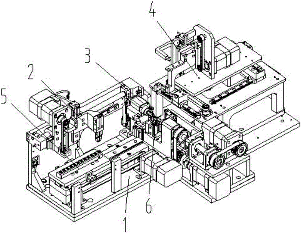
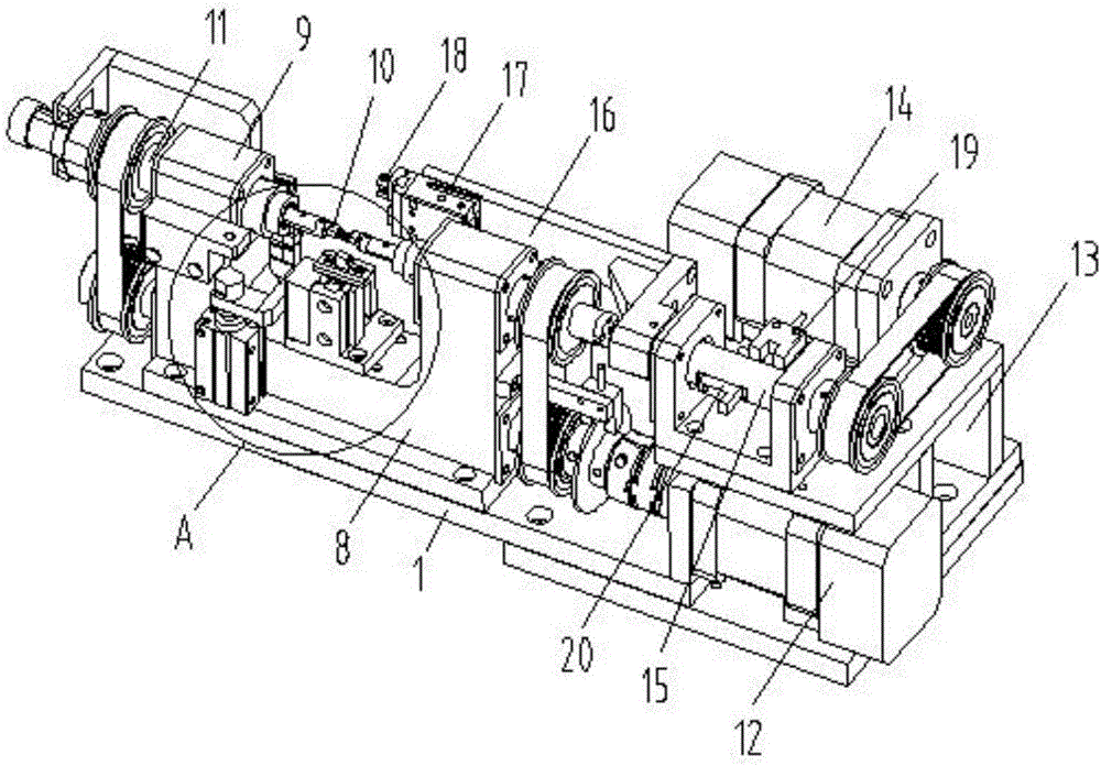
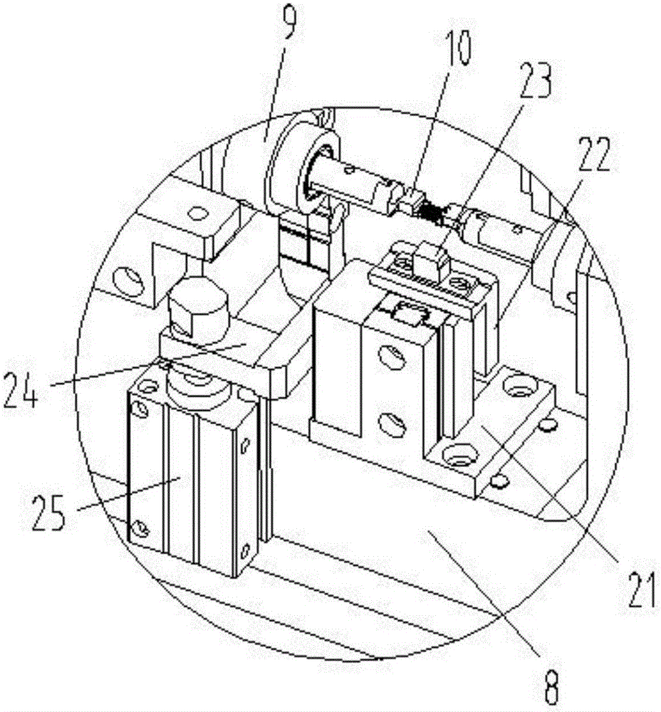
[0036] Such as Figure 1-Figure 8 As shown, the specific structure of the present invention is: a winding machine for a transformer skeleton, which includes a support plate 1, and the support plate 1 is provided with a winding mechanism 3 and a wire releasing device 4 that cooperate with each other. The winding mechanism 3 includes a winding seat 8 arranged on the support plate 1, the winding seat 8 is provided with two winding shafts 11 that cooperate with each other, and the outer ends of the winding shafts 11 are connected to To the winding motor 12, the inner end of the winding shaft 11 is connect...


PUM


Abstract

The invention relates to a winding machine for frameworks of transformers. The winding machine is characterized in that a winding mechanism and a pay-off device are arranged on a support plate, the winding mechanism comprises a winding seat, the winding seat is arranged on the support plate, winding rotary shafts are arranged on the winding seat, the outer ends of the winding rotary shafts are connected to a winding motor, feed cylinders are connected with the inner ends of the winding rotary shafts and are provided with clamp blocks which are matched with the frameworks of the transformers, the pay-off device comprises a pay-off seat, copper wires of a pay-off plate are arranged on the pay-off seat, a wire outlet is formed in the pay-off seat, a wiring block which is matched with the wire outlet is arranged on the winding seat and is matched with the altitudes of the clamp blocks, and wiring openings which are matched with the wire outlet are formed in the wiring block. The winding machine has the advantages that the feed cylinders are arranged on the winding rotary shafts, the clamp blocks which are matched with the frameworks of the transformers are arranged on cylinder heads of the feed cylinders, vertically downward wire outlet holes are formed in the pay-off device and are matched with the wiring block, and accordingly the copper wires can be uniformly wound on the frameworks of the transformers and can be prevented from twining and knotting.

Description

technical field [0001] The invention relates to the field of transformer processing equipment, in particular to a winding machine for a transformer frame. Background technique [0002] With the acceleration of the electrification process, the application of various electrical components is becoming more and more widespread, and the transformer is one of them. Most of the transformers are composed of a transformer skeleton and a coil wound on it. In the process, it is necessary to carry out winding processing on the skeleton of the transformer. [0003] Most of the existing winding equipment for transformer skeletons fix the transformer on the turntable, and the winding of the transformer is realized through the rotation of the turntable. When winding, it is necessary to stop the machine frequently to adjust the position of the winding, so that the copper wire is relatively uniform. Winding on the transformer skeleton, using this method for winding, consumes a lot of manpowe...

Claims


Application Information

Patent Timeline
IPC IPC(8): H01F41/082H01F41/098H01F41/096H01F41/06
CPCH01F41/06H01F41/082H01F41/096H01F41/098
Inventor 邓君黄红梅邓凯李培
Owner 威海合益电子科技有限公司
Learn More