Fully-sealed SMIF system

A fully enclosed, sealing ring technology, used in electrical components, conveyor objects, transportation and packaging, etc., can solve problems such as bodily injury, treatment process influence, and cannot exceed a certain value, and achieve increased sealing and good sealing performance. , the effect of avoiding leakage

Pending Publication Date: 2017-05-17
SHANGHAI FORTREND TECH CO LTD
View PDF11 Cites 13 Cited by
  • Summary
  • Abstract
  • Description
  • Claims
  • Application Information

AI Technical Summary

Problems solved by technology

Among the various processes for processing wafers, one process needs to be transported to another process for processing, and the process of handling generally needs to be completed manually, because there will be some toxic gases or Toxic dust, for example, in some processes, the wafer needs to be exposed to the environment of heavy metal ion mist, because the container carrying the wafer is manually transported to the semiconductor front-end module, and at the interface between the semiconductor equipment manufacturing front-end module and the process's sealed environment And when the container carrying the wafer is opened and the wafer is transported to the process, because the sealing performance of the mechanical seal is not very satisfactory, there will be a small amount of toxic gas entering the manual operation space from the process, and the workers are operating The process will absorb these heavy metal ions, causing harm to the body
And different processes have different requirements on the environment. Some processes need to ensure that the surrounding environment is relatively clean, or require a dry operating environment, and the humidity cannot exceed a certain value. If the front-end module and The sealing environment interface of the process and the container carrying the wafer are opened, and the wafer is transported to the process of the process. If the sealing is not good, it will affect the process of the process.

Method used


Image

  • Fully-sealed SMIF system
  • Fully-sealed SMIF system
  • Fully-sealed SMIF system

Examples


Embodiment Construction

[0033] In order to make the technical means, creative features, goals and effects achieved by the present invention easy to understand, the following embodiments describe the fully enclosed SMIF system of the present invention in detail in conjunction with the accompanying drawings.

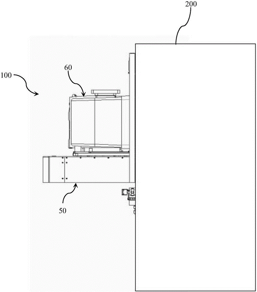
[0034] Such as figure 1 As shown, the fully enclosed SMIF system 100 is installed on one side of the box body 200 , and the fully enclosed SMIF system 100 is used to open the container 60 and deliver the products in the container 60 to the sealed box body 200 . In this embodiment, the product in the container 60 is a wafer. The box body 200 is provided with a processing device for processing semiconductors, and one side of the box body 200 is provided with an opening. The box body 200 is a sealed box with an opening, or a sealed room with an opening.

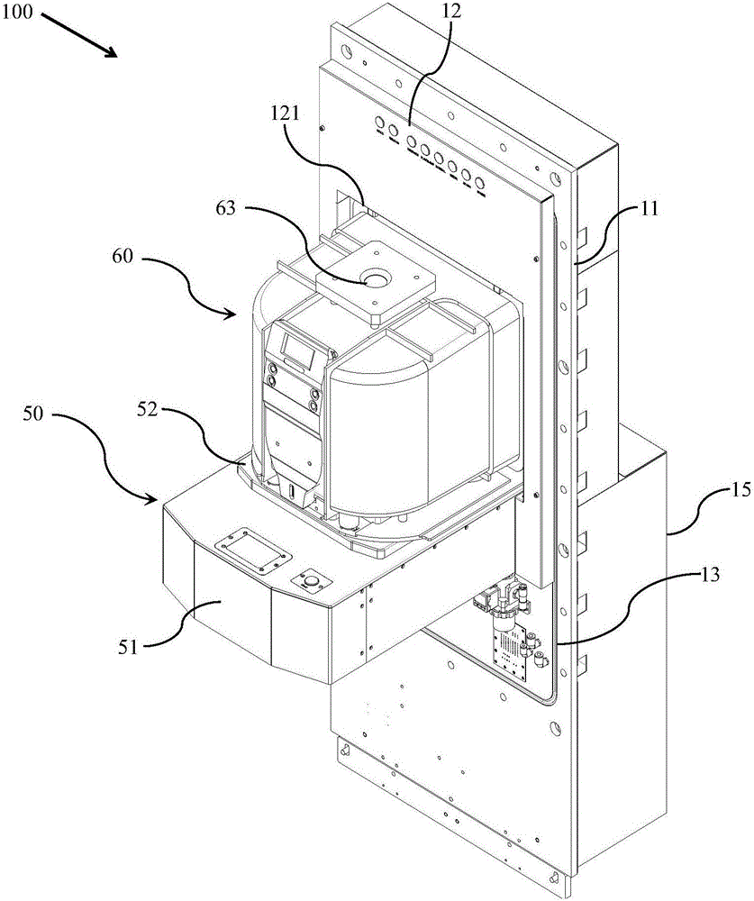
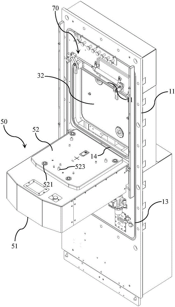
[0035] Such as figure 2 , image 3 , Figure 4 As shown, the fully enclosed SMIF system 100 includes: a mounting plate 11 , a lifting part, ...


PUM


Abstract

The invention provides a fully-sealed SMIF system. A first air nozzle hole is formed in a forwarding plate; air nozzles are mounted on a bearing platform; an air inlet hole and a pressure exhausting valve are arranged at the bottom of a container, so that gas replacement in the container can be realized; a first sealing ring is arranged between a mounting plate and the side surface of a box body, so that the system sealing property is improved; a second sealing ring is arranged on the periphery of an operating port of the mounting plate; when the forwarding plate drives the container to move to an operating position, the container is in contact with the second sealing ring, so that the sealing property between the container and the operating port of the mounting plate can be improved; a third sealing ring is arranged on one surface, towards the container, of a box opening plate, so that the sealing property between the box opening plate and the operating port of the mounting plate can be improved; a box opening part, a lifting part and a detection part are all arranged in the box body, so that maintenance can be performed conveniently; and therefore, the fully-sealed SMIF system is high in sealing property, and exchange of dust, gas and water vapor between the environment in the box body and the environment outside the box body can be well avoided.

Description

technical field [0001] The invention belongs to the technical field of semiconductors, and in particular relates to a fully enclosed SMIF system. Background technique [0002] Currently, in the semiconductor manufacturing process, wafer handling is critical to IC manufacturing. In order to ensure the quality of wafers when they are transported between different processes and avoid dust particles or other contamination of wafers, more and more transport work uses standard transport containers, that is, standard mechanical interface (SMIF for short) )technology. For example, US Patent Publication No. US4532970 "Semiconductor Processing Front-End Module in Dust Environment" and US Patent Publication No. US4534389 "Automatic Door for Semiconductor Front-End Module" disclose a SMIF system. The system reduces the contamination of the wafer by dust particles by significantly reducing the flow of dust particles through the wafer. This effect is achieved by mechanically ensuring t...

Claims


Application Information

Patent Timeline
Patent Type & Authority Applications(China)
IPC IPC(8): H01L21/677
CPCH01L21/67739H01L21/6776H01L21/67775H01L21/67778
Inventor 吴功
Owner SHANGHAI FORTREND TECH CO LTD
Why Eureka
Try Eureka