
Dielectric radiator unit and antenna device
A radiating unit and dielectric technology, which is applied in the structural form of radiating elements, antennas, antenna coupling, etc., can solve the problem that the dielectric resonant antenna cannot meet the characteristics of miniaturization and broadband at the same time
- Summary
- Abstract
- Description
- Claims
- Application Information
AI Technical Summary
Problems solved by technology
Method used
Image

Examples
Embodiment Construction
[0025] Embodiments of the present invention are described in detail below:
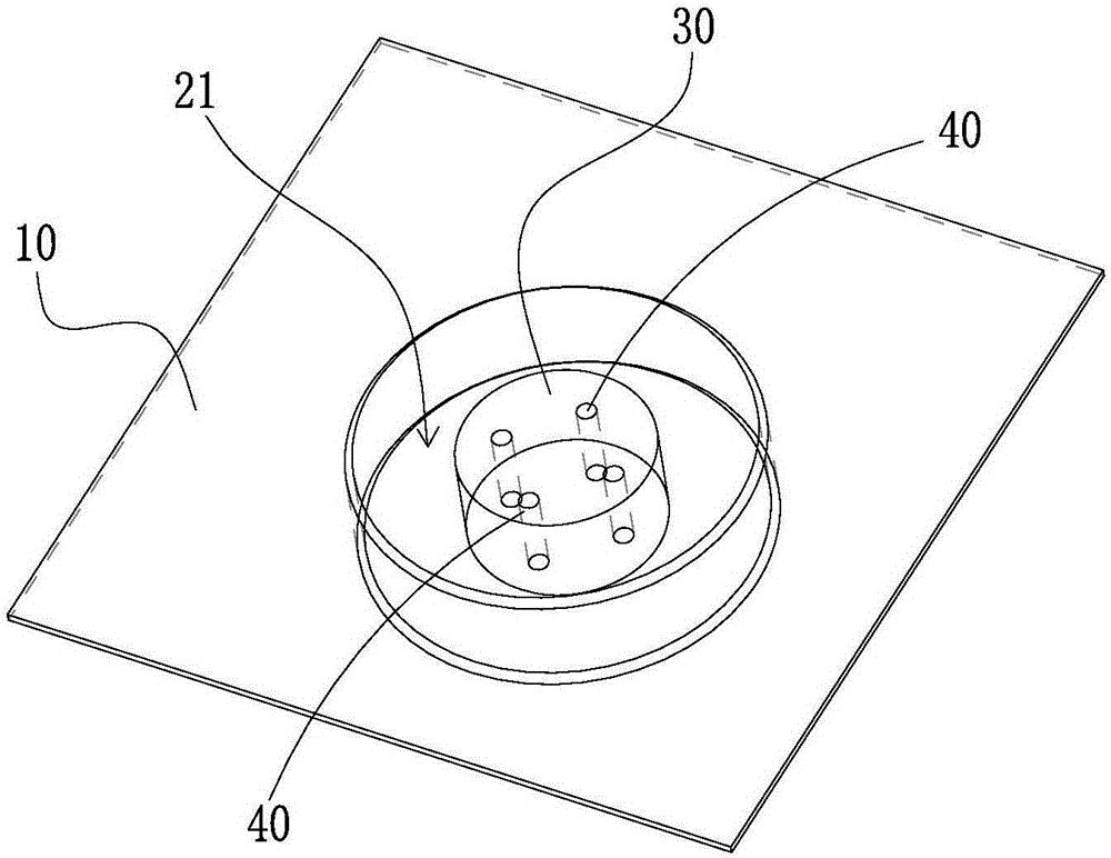
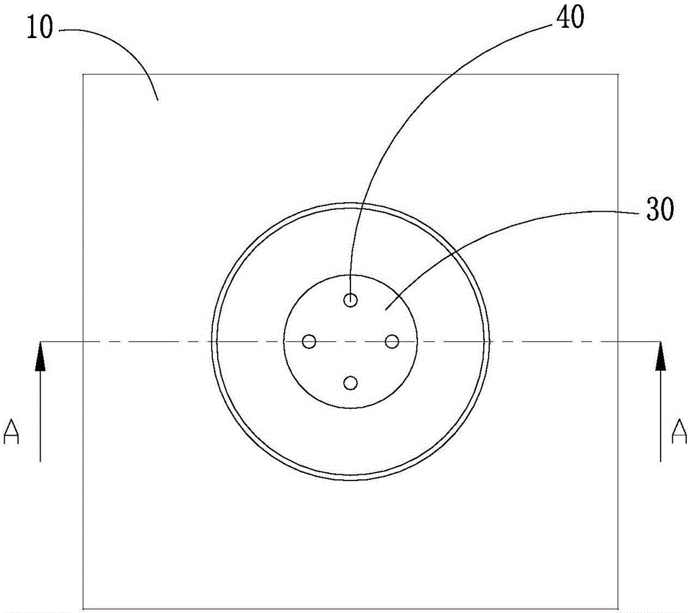
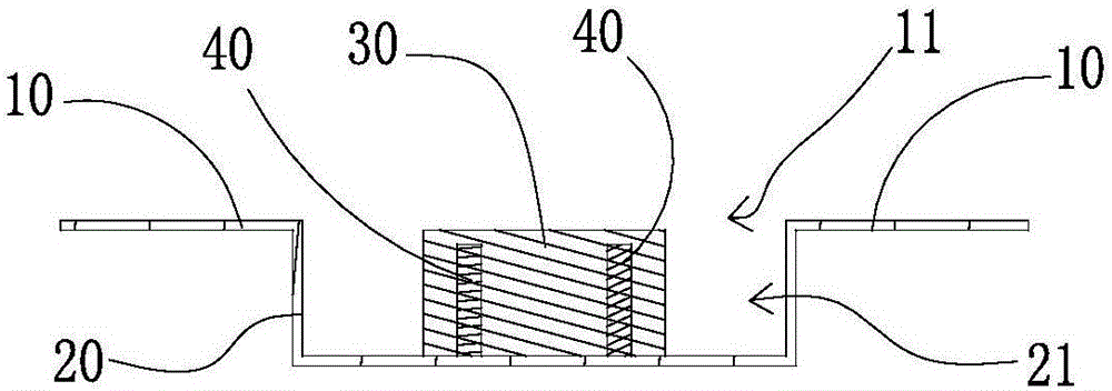
[0026] Such as Figure 1 to Figure 7 As shown, a dielectric radiation unit according to an embodiment of the present invention includes: a metal reflector 10 , a metal shell 20 , a dielectric resonator 30 and an excitation mechanism.
[0027] The metal reflector 10 is provided with an opening area 11 . The metal shell 20 is provided with a resonant cavity 21 with one end open. The opening end of the resonant cavity 21 is set corresponding to the opening area 11 . And the metal shell 20 is electrically connected or insulatedly connected to one side of the metal reflector 10 through an insulator. In this embodiment, the open end of the metal shell 20 can be fixed to the opening area 11 of the metal reflector 10 by welding or bolted, so that the open end of the metal shell 20 and the metal reflector 10 are in electrical contact with each other; of course , There may also be a gap between the open end...
PUM
 Abstract
Description
Claims
Application Information