Cable ladder

A cable ladder frame and cable technology, applied in the direction of pipe support, electrical components, rod connection, etc., can solve the problems that it is difficult to change the structure, the assembly operation is difficult, etc., and achieve the effect of easy operation and strong clamping system

Active Publication Date: 2017-05-17
APARELLAJE ELECTRICO
View PDF6 Cites 3 Cited by
  • Summary
  • Abstract
  • Description
  • Claims
  • Application Information

AI Technical Summary

Problems solved by technology

[0007] The disadvantage of metal cable ladders is that their assembly operations, attaching the crossbars to the side rails, are often difficult and require specific tools
Also, once the cable ladder frame is assembled, it is very difficult to change its configuration

Method used


Image

  • Cable ladder
  • Cable ladder
  • Cable ladder

Examples


Embodiment Construction

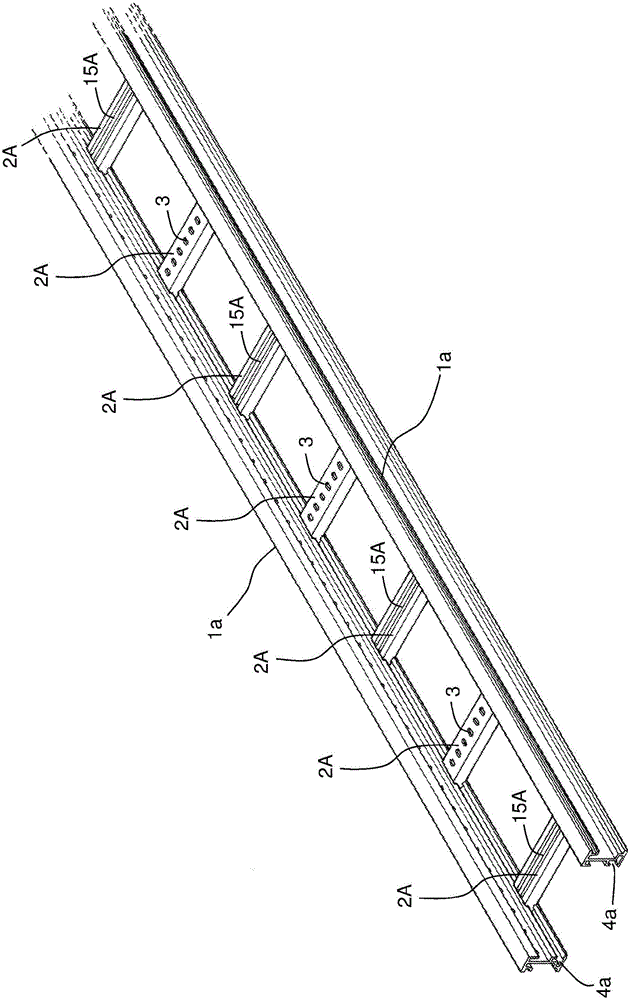
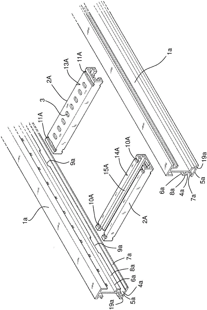
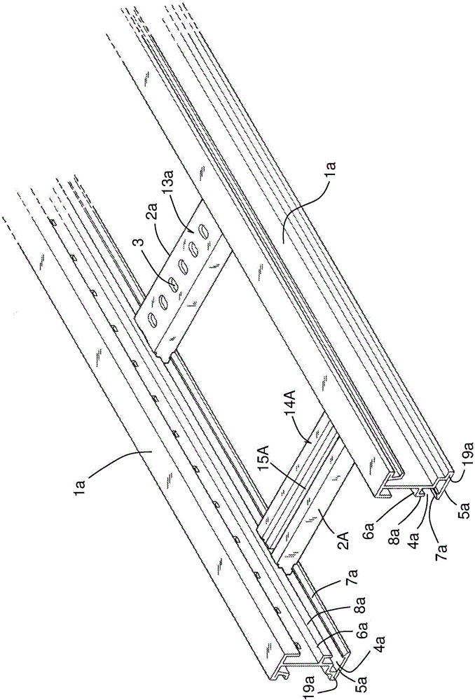
[0043] Figure 1-4 A first embodiment of a cable ladder frame according to the invention is shown. Such as figure 1 As shown, the cable ladder frame is formed by two parallel side rails 1a attached to each other by a plurality of parallel cross bars 2A regularly spaced from each other. The two side rails 1a are identical and arranged symmetrically with respect to each other. Each side rail consists of an extruded profile made of polymer material. An electrical insulating material with a surface resistivity greater than 100 MΩ, such as PVC (polyvinyl chloride), etc., is preferred as the polymer material. All crossbars 2A are identical and likewise consist of an extruded profile made of the same material as the side rails 1a. Similar to prior art cable ladders, the combination of cross bars 2A forms a discontinuous support surface for the cables on which the cables held by the cable ladder are laid. The installer can use different fastening means (not shown) to fix the cabl...


PUM


Abstract

The invention relates to a cable ladder formed by two beams (1a) and a number of crossbars (2A), all formed by extruded profiles made of a polymeric material. The beams (1) have a channel (4a) that receives a corresponding end of the crossbars. The channel (4a) has a lower wing (5a) and an upper wing (6a). A recess (7a, 8a) of the lower wing (5a) or upper wing (6a) has a number of openings (9a) along the longitudinal direction of the beam (1). The ends of the crossbars (2A) pass through the opening (9a) of the recess (8a) and have a reduction (10A) into which a corresponding part of the channel (4a) clips. The lower wing (5a) of the beams (1a) is folded over itself via a folding line (19a), such that a final section of the lower wing (5a) undergoes a lowering by means of elastic bending when the end of the crossbar (2A) is introduced.

Description

technical field [0001] The invention relates to a cable ladder consisting of two parallel side rails attached to each other by a plurality of parallel cross bars forming a discontinuous support surface for the cables. In particular, the invention relates to a cable ladder frame of the type in which the side rails and cross bars are characterized by: [0002] each said crossbar is an extruded profile made of a polymeric material; [0003] Each of said side rails is an extruded profile made of polymer material, each said side rail having a channel on its inner side facing the other side rail for receiving a respective end of said cross bar department; [0004] The channel of the side rail is delimited by a lower rib and an upper rib, the lower rib or the upper rib has a protrusion extending towards the inside of the channel at its end and is separated from each other in the longitudinal direction of the side rail. a plurality of spaced apart openings are formed in one of said...

Claims


Application Information

Patent Timeline
Patent Type & Authority Applications(China)
IPC IPC(8): H02G3/04
CPCF16B7/0473H02G3/0456F16L3/26
Inventor J·A·摩斯塔佐奥维多
Owner APARELLAJE ELECTRICO
Why Eureka
Try Eureka