Green belt trimmer

A green belt, trimmer technology, applied in agricultural machinery and implements, cutting tools, cutting equipment and other directions, can solve the problems of easy fatigue, low work efficiency, psoas muscle and wrist injury, etc., and achieves simple structure and flexible use of the device. Convenient and comfortable effect

Active Publication Date: 2017-05-24
NINGBO UNIV
6 Cites 4 Cited by

AI-Extracted Technical Summary

Problems solved by technology

The traditional green belt pruning tools are branch shears, which are manually operated by garden workers, which is labor-intensive and low-efficiency
In order to improve work efficiency and reduce labor intensity, automatic pruning machines have emerged as the times require, but because the top and both sides of the green belt have to be trimmed, when pruning the sides, the current auto...

Abstract

The invention discloses a green belt trimmer which comprises a main shell, an auxiliary shell, a blade and a blade rotating driving mechanism. The main shell and the auxiliary shell are separated, the blade rotating driving mechanism comprises a motor, a driving shaft and a blade shaft, the motor is fixedly arranged in the main shell, and the auxiliary shell is in coupling connection with the main shell and the auxiliary shell. The rear end of the driving shaft is coaxially and fixedly connected with an output shaft of the motor, a first bevel gear and a second bevel gear are arranged in the auxiliary shell, the first bevel gear is coaxially and fixedly connected with the front end of the driving shaft, and the blade shaft is in coupling connection with the auxiliary shell. The second bevel gear is coaxially and fixedly connected with the blade shaft, the first bevel gear and the second bevel gear are engaged, the blade is fixedly connected with the blade shaft, and the green belt trimmer is characterized in that a rotary engagement and disengagement mechanism is arranged between the auxiliary shell and the driving shaft. The green belt trimmer has the advantages that when a gardener trims the side face or inclined face of a green belt, the wrist does not need to twist along, the hand feeling is comfortable, and fatigue is relieved.

Application Domain

Technology Topic

EngineeringGreen belt +3

Image

  • Green belt trimmer
  • Green belt trimmer
  • Green belt trimmer

Examples

  • Experimental program(2)

Example Embodiment

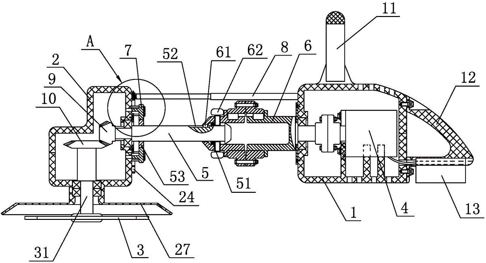
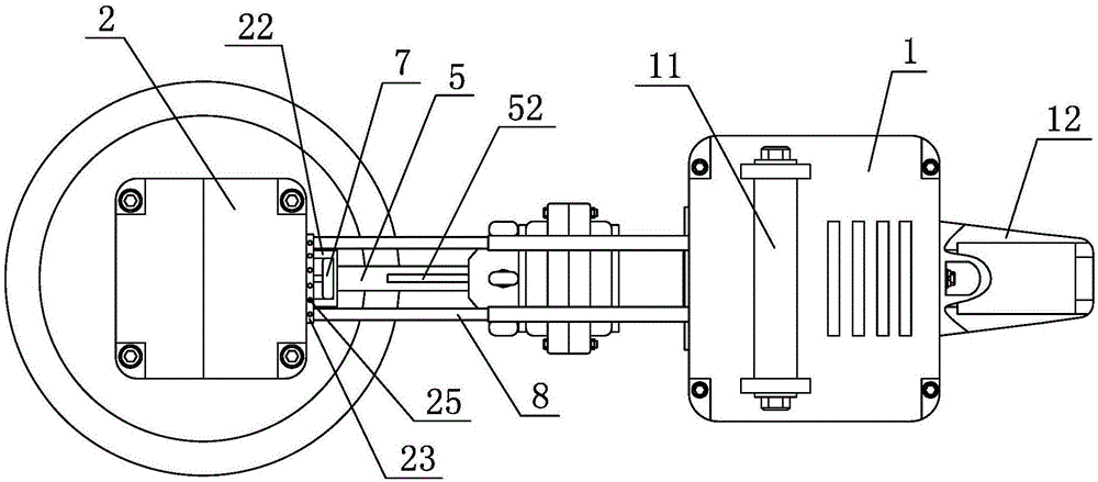
[0020] Embodiment 1: As shown in the figure, a green belt trimmer includes a main casing 1, a sub casing 2, a blade 3 and a blade rotation drive mechanism. The main casing 1 and the sub casing 2 are separated from each other, and the main casing The upper end surface of 1 is fixedly provided with a handle 11, the rear end of the main housing 1 is fixedly provided with a gripping handle 12, the blade rotation driving mechanism includes a motor 4, a drive shaft 5 and a blade shaft 31, and the motor 4 is fixedly provided on the main housing 1. In the drive shaft 5, an axial telescopic mechanism is provided. The axial telescopic mechanism includes a hollow shaft 6. The hollow shaft 6 is axially connected with the main housing 1, and the hollow shaft 6 is coaxially and fixedly connected with the output shaft of the motor 4. The rear end of 5 coaxially extends into the hollow shaft 6 and is axially slidingly fitted with the hollow shaft 6. A centering ring 51 is provided between the drive shaft 5 and the hollow shaft 6, and the centering ring 51 is coaxially sleeved on the drive shaft 5. The hollow shaft 6 is provided with a second key block 61, and the drive shaft 5 is provided with a sliding groove 52 extending in the axial direction. The second key block 61 is located in the sliding groove 52 and slidingly fitted with the sliding groove 52. The upper diameter of the hollow shaft 6 A positioning screw 62 is screwed to each other. The end of the positioning screw 62 abuts on the circumferential surface of the drive shaft 5. The front end of the drive shaft 5 is axially connected to the sub-housing 2, and there is provided between the sub-housing 2 and the drive shaft 5. Rotating clutch mechanism, the rotating clutch mechanism includes a clutch block 7, the clutch block 7 is sleeved on the drive shaft 5, the drive shaft 5 is fixedly provided with a first key block 53, the clutch block 7 is provided with a first key block 53 The keyway 71 of the clutch block 7 is integrally provided with pins 72 on the side of the clutch block 7 facing the sub-housing 2. The side wall of the sub-housing 2 is provided with a socket 21 for inserting the pins 72, and the side wall of the sub-housing 2 A stop ring 22 is fixedly provided, and the stop ring 22 is sleeved on the clutch block 7. When the blade 3 is rotated for trimming the green belt, the pin 72 of the clutch block 7 is inserted into the socket 21 of the auxiliary housing 2, and the drive shaft 5 When turning, the auxiliary housing 2 does not move. When the angle of the blade 3 needs to be adjusted, the pin 72 of the clutch block 7 is separated from the socket 21 of the auxiliary housing 2, and the keyway 71 of the clutch block 7 and the first key block of the drive shaft 5 53 is matched, the drive shaft 5 drives the auxiliary housing 2 to rotate together through the clutch block 7. A positioning mechanism is provided between the auxiliary housing 2 and the main housing 1. The positioning mechanism includes a connecting rod 8, which is a telescopic rod. The rod 8 is parallel to the drive shaft 5, the rear end of the connecting rod 8 is fixedly connected to the main housing 1, and the side wall of the auxiliary housing 2 is fixedly provided with a positioning convex ring 23 coaxial with the driving shaft 5, and a positioning convex ring 23 A coaxial positioning ring groove 24 is provided on the locating ring groove 24, the front end of the connecting rod 8 is inserted into the locating ring groove 24, the positioning convex ring 23 is provided with a plurality of radial positioning holes 25 evenly distributed in the circumferential direction, and a positioning pin 26 is inserted into one of them The radial positioning hole 25 is inserted and fixed with the connecting rod 8. A first bevel gear 9 and a second bevel gear 10 are arranged in the auxiliary housing 2. The first bevel gear 9 is coaxially and fixedly connected with the front end of the drive shaft 5. The shaft 31 is axially connected to the auxiliary housing 2, the second bevel gear 10 is coaxially fixedly connected with the blade shaft 31, the first bevel gear 9 is meshed with the second bevel gear 10, the blade 3 is fixedly connected to the blade shaft 31, and the auxiliary housing A baffle 27 is fixed on the body 2, and the baffle 27 covers the blade 3 .

Example Embodiment

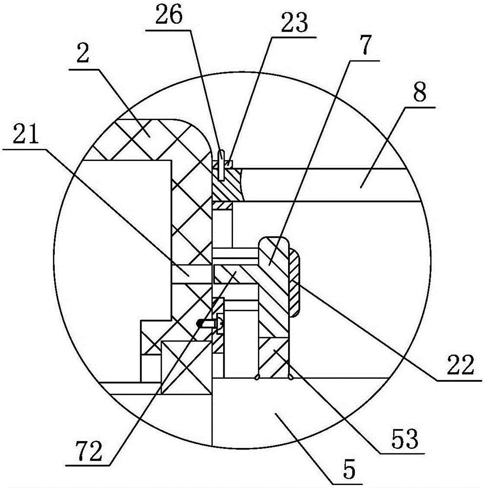
[0021] Embodiment 2: As shown in the figure, a green belt trimming machine includes a main casing 1, a sub casing 2, a blade 3 and a blade rotation drive mechanism. The main casing 1 and the sub casing 2 are separated from each other, and the main casing The upper end surface of 1 is fixedly provided with a handle 11, the rear end of the main housing 1 is fixedly provided with a gripping handle 12, the blade rotation driving mechanism includes a motor 4, a drive shaft 5 and a blade shaft 31, and the motor 4 is fixedly provided on the main housing 1. Among them, the drive shaft 5 is axially connected with the main housing 1 and the auxiliary housing 2 respectively, the rear end of the drive shaft 5 is coaxially fixedly connected with the output shaft of the motor 4, and a rotating shaft is arranged between the auxiliary housing 2 and the drive shaft 5. The clutch mechanism, the rotary clutch mechanism includes a clutch block 7, the clutch block 7 is sleeved on the drive shaft 5, the drive shaft 5 is fixedly provided with a first key block 53, the clutch block 7 is provided with a first key block 53 The keyway 71, the side of the clutch block 7 facing the sub-housing 2 is integrally provided with pins 72, the side wall of the sub-housing 2 is provided with a socket 21 for inserting the pins 72, and the side wall of the sub-housing 2 is fixed A stop ring 22 is provided, and the stop ring 22 is sleeved on the clutch block 7. When the blade 3 is rotated to trim the green belt, the pin 72 of the clutch block 7 is inserted into the socket 21 of the auxiliary housing 2, and the drive shaft 5 rotates , The auxiliary housing 2 does not move. When the angle of the blade 3 needs to be adjusted, the pins 72 of the clutch block 7 are separated from the socket 21 of the auxiliary housing 2, and the keyway 71 of the clutch block 7 and the first key block 53 of the drive shaft 5 In cooperation, the drive shaft 5 drives the auxiliary housing 2 to rotate together through the clutch block 7. A positioning mechanism is provided between the auxiliary housing 2 and the main housing 1. The positioning mechanism includes a connecting rod 8, which is a telescopic rod. 8 is parallel to the drive shaft 5, the rear end of the connecting rod 8 is fixedly connected to the main housing 1, a positioning convex ring 23 coaxial with the drive shaft 5 is fixed on the side wall of the auxiliary housing 2, and the positioning convex ring 23 A coaxial positioning ring groove 24 is provided. The front end of the connecting rod 8 is inserted into the positioning ring groove 24. The positioning convex ring 23 is provided with a plurality of radial positioning holes 25 evenly distributed in the circumferential direction. The positioning pins 26 are inserted into one of the diameters. The first bevel gear 9 and the second bevel gear 10 are arranged in the auxiliary housing 2 and the first bevel gear 9 is coaxially fixedly connected with the front end of the drive shaft 5, and the blade shaft 31 is axially connected with the auxiliary housing 2, the second bevel gear 10 is coaxially fixedly connected with the blade shaft 31, the first bevel gear 9 is meshed with the second bevel gear 10, the blade 3 is fixedly connected with the blade shaft 31, and the auxiliary housing 2 is fixedly provided with a baffle 27, which covers the blade 3.
[0022] In the first and second embodiments above, the motor 4 is a DC motor, a battery 13 is arranged in the main housing 1, and the DC motor is electrically connected to the battery 13.
[0023] In the above embodiment, the process of adjusting the angle of the blade 3 is as follows: pull out the clutch block 7 from the secondary housing 2, disengage the pins 72 of the clutch block 7 from the socket 21 of the secondary housing 2, and make the keyway of the clutch block 7 71 is matched with the first key block 53 of the drive shaft 5, and then the motor 4 is controlled to drive the drive shaft 5 to rotate to a certain angle, the drive shaft 5 drives the clutch block 7 to rotate, and the clutch block 7 drives the auxiliary housing 2 to rotate together through the gear ring 22 At the same time, pull out the positioning pin 26 on the positioning convex ring 23, the positioning convex ring 23 rotates synchronously with the auxiliary housing 2, and the front end of the connecting rod 8 is in sliding fit with the positioning ring groove 24 in the positioning convex ring 23. After the body 2 is rotated in place, that is, after the angle of the blade 3 is adjusted in place, the motor 4 stops working, inserts the positioning pin 26 into the radial positioning hole 25 of the positioning convex ring 23 and inserts and fixes it with the connecting rod 8, and then pushes the clutch block 7 , The keyway 71 of the clutch block 7 is slid away from the first key block 53 of the drive shaft 5, and the pin 72 of the clutch block 7 is inserted into the socket 21 of the auxiliary housing 2. At this time, the motor 4 drives the drive shaft 5 to rotate, and the auxiliary housing The body 2 does not move, and the drive shaft 5 drives the blade 3 to rotate through the engagement of the first bevel gear 9 and the second bevel gear 10 to realize the trimming of the green belt.

PUM

no PUM

Description & Claims & Application Information

We can also present the details of the Description, Claims and Application information to help users get a comprehensive understanding of the technical details of the patent, such as background art, summary of invention, brief description of drawings, description of embodiments, and other original content. On the other hand, users can also determine the specific scope of protection of the technology through the list of claims; as well as understand the changes in the life cycle of the technology with the presentation of the patent timeline. Login to view more.

Similar technology patents

Indoor unit of wall-mounted air conditioner

Owner:QINGDAO HAIER AIR CONDITIONER GENERAL CORP LTD

Classification and recommendation of technical efficacy words

  • Reduce fatigue
  • Feel comfortable

Dictation selection

ActiveUS8032372B1Reduce fatigueReduce physical stressNatural language translationComputer-assisted medical data acquisitionMedical transcriptionFeature set
Owner:DELIVERHEALTH SOLUTIONS LLC

Locking hinge connector apparatus

InactiveUS20060016047A1Reduce back strainReduce fatigueBrush bodiesHingesHinge angleEngineering
Owner:BLACKMAN GARY PALMER +1

Gel grip controller

InactiveUS20050275165A1Feel comfortableControlling membersGlovesEngineeringMulti directional
Owner:INTEC INC

Process for preparing flexible polyurethane foam plastic

InactiveCN1463997AUniform and dense cell sizeFeel comfortableIsocyanateFire retardant
Owner:SHANXI INST OF COAL CHEM CHINESE ACAD OF SCI

Metal micro-needle array flexible patch, transdermal applicator and transdermal application patch

ActiveCN103203072AImprove consistency and controlFeel comfortableMicroneedlesMedical devicesDrugNeedle holder
Owner:SHANGHAI RUNTONG MEDICAL TECH CO LTD

Production process of anti-staining automobile interior leather

ActiveCN103602764AAnti-aging leather bodyFeel comfortableTanning treatmentPre-tanning chemical treatmentDyeingEngineering
Owner:HAINING SENDE LEATHER
Why Eureka
Try Eureka