A metal material straightening machine

A metal material, straightening machine technology, applied in the field of metal material straightening machine, can solve the problems of inconvenient operation, inaccurate working parameters, poor adaptability of metal workpieces, etc., to improve stability and work efficiency, wide application range, Reliable effect

Active Publication Date: 2019-03-08
苏州科弗曼机械有限公司
View PDF5 Cites 0 Cited by
  • Summary
  • Abstract
  • Description
  • Claims
  • Application Information

AI Technical Summary

Problems solved by technology

[0002] The precise alignment of industrial components is a common problem in the modern manufacturing industry and needs to be solved urgently. Its working method is to use the principle of residual deformation after metal plastic deformation, and to make the workpiece to be aligned under the condition of active loading. The plastic deformation in the opposite direction, when the residual deformation of the plastic deformation is equal to the error amount, the alignment of the workpiece is realized. At present, most of the alignment work in our country is manually operated by experience, with low efficiency and poor precision, making the industry The application of component plastic deformation straightening technology is greatly restricted
[0003] In the prior art, the size range of workpieces that can be straightened by the metal straightening machine has obvious limitations, the working parameters for workpiece straightening are not accurate, and the adaptability to different forms of metal workpieces is poor, and only a single form of metal workpiece can be processed , some straightening machines are too complicated in structure and inconvenient to operate, so they are limited in production and use, so metal straightening processing machines with good adaptability, simple structure and easy operation are needed

Method used


Image

  • A metal material straightening machine
  • A metal material straightening machine
  • A metal material straightening machine

Examples


specific Embodiment approach

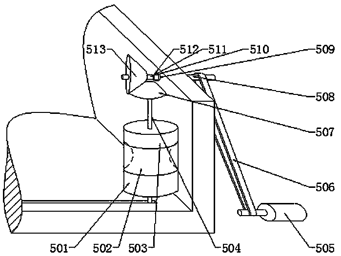
[0024] Specific embodiments: when the operator uses the present invention, the operator measures the size of the object to be aligned, and installs the gear shaft 511 on the drive shaft 508 according to the size of the object to be aligned. The size of the object is determined by observing the scale on the gear shaft 511 to determine the installation position of the gear shaft 511. After the position is determined, the positioning pin 512 is fixed in the positioning hole 510, and the installation of the bevel gear 2 513 is completed. Metal materials of different sizes are straightened, which solves the shortcoming of the narrow application range of the straightening machine.

[0025] After completing the installation of bevel gear 2 513, the operator judges whether the straightening object is a hollow shaft, and if it is a hollow shaft material, install the arc-shaped roller 502 on the upper end of the lower roller 501, and then install the upper roller 503 on the arc-shaped ro...


PUM


Abstract

The invention provides a metal material straightening machine, comprising a screw rod, a threaded hole connection block, a belt I, a motor I, a connecting shaft, a bevel gear I, a bevel gear II, a rotating shaft, a gear shaft, a locating hole and a locating pin, wherein the screw rod is connected to the motor I through the belt I, and the threaded hole connection block is connected to the screw rod. The distance between left and right rollers in the invention is adjusted easily through this design, and the problem of uneasy adjustment of the distance between the left and right rollers is solved. The lower end of the connecting shaft is connected to the threaded hole connection block through a bearing II, and the upper end of the connecting shaft is connected to the bevel gear I fit to the bevel gear II installed on the gear shaft; the gear shaft is installed on the left end of a drive shaft through the locating hole and the locating pin. Straightening metal materials in different sizes is achieved through this design, and the disadvantage of narrow application scope of the straightening machine is overcome. The metal material straightening machine provided by the invention has the advantages of simple structure, wide application scope, easy operation and high reliability.

Description

technical field [0001] The invention relates to a metal material straightening machine, which belongs to the field of metal material straightening equipment. Background technique [0002] The precise alignment of industrial components is a common problem in the modern manufacturing industry and needs to be solved urgently. Its working method is to use the principle of residual deformation after metal plastic deformation, and to make the workpiece to be aligned under the condition of active loading. The plastic deformation in the opposite direction, when the residual deformation of the plastic deformation is equal to the error amount, the alignment of the workpiece is realized. At present, most of the alignment work in our country is manually operated by experience, with low efficiency and poor precision, making the industry The application of component plastic deformation straightening technology has been greatly restricted. [0003] In the prior art, the size range of work...

Claims


Application Information

Patent Timeline
Patent Type & Authority Patents(China)
IPC IPC(8): B21D1/02B21D3/05
CPCB21D1/02B21D3/05
Inventor 蒋伟
Owner 苏州科弗曼机械有限公司
Why Eureka
Try Eureka