Top plate drilling device and application method thereof

A drilling device and top plate technology, applied in metal processing equipment, metal processing machinery parts, manufacturing tools, etc., can solve the problems of lack of convenient positioning and fixed electric drill auxiliary tools for drilling operations, insecure quality, large construction volume, etc.

Inactive Publication Date: 2017-05-24
湖南省第五工程有限公司
View PDF10 Cites 2 Cited by
  • Summary
  • Abstract
  • Description
  • Claims
  • Application Information

AI Technical Summary

Problems solved by technology

The above-mentioned construction is generally carried out on the roof of the room. The construction volume of the drilling is large, and the drilling center and drilling depth must meet the relevant standard requirements. During the drilling construction process, conditions are usually created to make the construction When people approach the top of the slab or beams to drill holes, the auxiliary facilities are usually platforms or escalators for construction workers to work on, that is, to build scaffolding or stairs for drilling construction. This method takes a long time, consumes a lot of materials, and is subject to Site restrictions, workspaces that affect other operations
The auxiliary facilities in the prior art are labor-intensive and cost-increasing; and the quality is not guaranteed, the safety is not reliable, the gain outweighs the loss, and half the result with twice the effort
In a word, in the prior art, there is no auxiliary tool for positioning and fixing the electric drill to facilitate the drilling operation.

Method used


Image

  • Top plate drilling device and application method thereof

Examples


Embodiment Construction

[0025] In order to make the object, technical solution and advantages of the present invention clearer, the present invention will be further described in detail below in conjunction with the accompanying drawings and embodiments. It should be understood that the specific embodiments described here are only used to explain the present invention, not to limit the present invention.

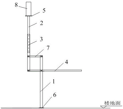
[0026] see figure 1 , figure 1 It is a structural schematic diagram of the roof drilling device provided by the present invention.

[0027] An embodiment of the present invention provides a roof drilling device, the roof drilling device includes: a vertical rod 1, a support rod, a handle rod 5 and a connecting rod 7; wherein,

[0028] One end of the vertical rod 1 is hinged with an end of the connecting rod 7, one end of the supporting rod is hinged with an end of the handle bar 5, and the other end of the supporting rod is fixed with an electric drill 8; the connecting rod 7 The other end of ...


PUM


Abstract

The invention provides a top plate drilling device and an application method thereof. The top plate drilling device comprises a vertical rod, a supporting rod, a handle rod and a connecting rod. One end of the vertical rod is hinged to one end of the connecting rod. One end of the supporting rod is hinged to one end of the handle rod. An electric drill is fixed to the other end of the supporting rod. The other end of the connecting rod is hinged to the position, located above the hinged end of the supporting rod and the handle rod, of the supporting rod. The position, located below the hinged end of the vertical rod and the connecting rod, of the vertical rod is hinged to the handle rod. A parallelogram is enclosed by the supporting rod, the connecting rod, the handle rod and the vertical rod in the hinged positions. The top plate drilling device has the beneficial effects that the structure is simple; installation is convenient; drilling operation can be completed on a floor slab by workers; and the labor intensity of the workers is relieved.

Description

technical field [0001] The invention relates to the technical field of construction, in particular to a roof drilling device and a method for using the same. Background technique [0002] In the construction process of construction projects, it is usually necessary to drill holes on the slab roof or beams, such as: structural column reinforcement in masonry engineering; installation of hanging brackets in electromechanical installation engineering; installation of ceiling suspenders in decoration engineering. The above-mentioned construction is generally carried out on the roof of the room. The construction volume of the drilling is large, and the drilling center and drilling depth must meet the relevant standard requirements. During the drilling construction process, conditions are usually created to make the construction When people approach the top of the slab or beams to drill holes, the auxiliary facilities are usually platforms or escalators for construction workers to...

Claims


Application Information

Patent Timeline
IPC IPC(8): B23Q1/76
CPCB23Q1/76
Inventor 焦鹤龙兴龙新乐颜昌明李高健李建新鲁滔李桂新周剑段睿
Owner 湖南省第五工程有限公司
Why Eureka
Try Eureka