Bearing roller spherical surface superfinishing mechanism

A technology of bearing rollers and sliding mechanism, which is applied to superfinishing machines, grinding workpiece supports, metal processing equipment, etc. , convenient for loading and unloading and the effect of processing workpieces of different shapes

Active Publication Date: 2017-05-24
XINCHANG COUNTY CHENGBEN ROLLER BEARING
View PDF7 Cites 10 Cited by
  • Summary
  • Abstract
  • Description
  • Claims
  • Application Information

AI Technical Summary

Problems solved by technology

[0003] The purpose of the present invention is to overcome the defects of low processing efficiency and processing accuracy during the existing spherical grindin

Method used


Image

  • Bearing roller spherical surface superfinishing mechanism
  • Bearing roller spherical surface superfinishing mechanism
  • Bearing roller spherical surface superfinishing mechanism

Examples


Embodiment approach 1

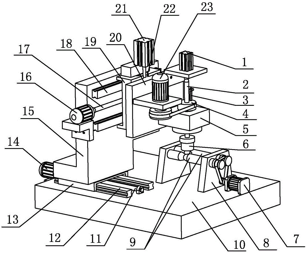
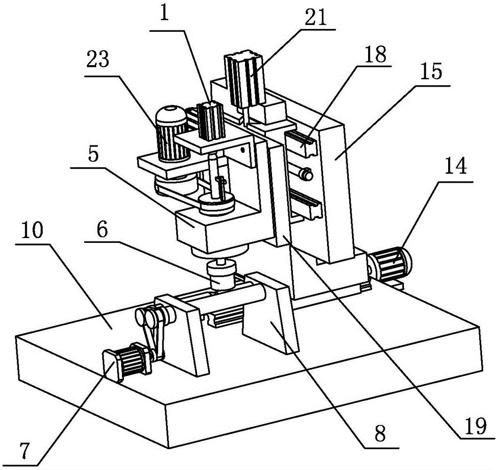
[0025] Such as Figure 1~Figure 3As shown, the present invention includes a bed 10 and a workpiece support mechanism installed on the bed 10, a workpiece drive device, a cutter device, a control system and an automatic loading and unloading mechanism, and the cutter device includes a mounting support 14, a whetstone 6, and a whetstone drive mechanism , X-axis sliding mechanism, Y-axis sliding mechanism and Z-axis feed mechanism, the X-axis sliding mechanism includes an X-axis sliding plate 13, an X-axis sliding guide mechanism, an X-axis screw pair and an X-axis sliding drive The motor 14, the X-axis sliding guide mechanism is an X-axis guide rail pair distributed along the X-axis direction, the guide rail 12 of the X-axis guide rail pair is fixedly installed on the top surface of the bed 10 along the X-axis direction, and the X-axis sliding plate 13 is fixedly installed on the On the slider of the X-axis guide rail pair, the mounting support 14 is fixedly installed on the X-a...

Embodiment approach 2

[0028] As another embodiment, when the outer circular surfaces of the two supporting rollers 9 are cylindrical surfaces, the two supporting rollers 9 are separated by a certain distance, but the distance between the two supporting rollers 9 is not greater than that of the spherical roller workpiece to be processed. The outer diameter of the workpiece support is formed between the two support rollers 9, and the workpiece backer is arranged between the two support rollers 9. The workpiece backer is provided with two abutting parts at a certain distance in the axial direction of the support roller 9. When the workpiece is to be processed When the spherical roller workpiece is placed on the workpiece supporting part, the two ends of the workpiece respectively abut against the two abutting parts so as to position the workpiece. Through the sliding adjustment of the X-axis sliding mechanism, when When the workpiece curvature center plane is located in the center line of the workpiece...

Embodiment approach 3

[0030] As another embodiment, two workpiece support parts can also be arranged in the axial direction between the two support rollers. The support rollers on both sides corresponding to one workpiece support part are cylindrical surfaces, and the other workpiece support part The support roller on the corresponding side is provided with a V-shaped annular groove, and the support roller on the other side is a cylindrical surface. In this way, spherical rollers of different shapes can be ground on the same grinding mechanism, which improves the processing efficiency.


PUM


Abstract

The invention relates to a bearing roller spherical surface superfinishing mechanism, and belongs to the technical field of bearing roller superfinishing. The bearing roller spherical surface superfinishing mechanism comprises a lathe bed, a workpiece supporting mechanism, a workpiece driving device, a cutter device and a control system, wherein the workpiece supporting mechanism, the workpiece driving device, the cutter device and the control system are arranged on the lathe bed. The cutter device comprises an installation support, an oil stone, an oil stone driving mechanism and a Z-axis feeding mechanism; the working end of the oil stone is in a cylindrical shape; the inner diameter of the oil stone is larger than the chord length of the arc shape of a spherical roller to be machined; the oil stone is driven by a servo motor of the oil stone driving mechanism to rotate by adopting an oil stone central axis as a center; the workpiece supporting mechanism is arranged under the oil stone, and comprises a support and two horizontal cylindrical support rollers supported on a central axis of the support and parallel to each other; a workpiece supporting part is formed between the cylindrical surfaces of the two supporting rollers; the two supporting rollers are driven by the workpiece driving device to rotate towards the same direction at the same speed; and each mechanism is controlled by the control system. The bearing roller spherical surface superfinishing mechanism provided by the invention overcomes the defects of low machining efficiency and low machining accuracy during existing workpiece spherical surface superfinishing.

Description

technical field [0001] The invention belongs to the technical field of superfinishing of bearing rollers, and in particular relates to a spherical surface grinding mechanism of bearing rollers. Background technique [0002] Parts such as bearing rings and rolling elements have spherical surfaces, which are formed by the rotation of the busbar around the center line. There are three main shapes of the sphere, the first is that the busbar is arc-shaped; the second is that the middle section of the busbar is a straight line, the two ends are arc slopes, and the center of curvature of both ends is the same; the third is that the middle section of the busbar is a straight line, and the two ends are arcs Slopes do not each have an independent center of curvature. The center of curvature is the position point of the arc center of the generatrix, and the position points of the generatrix forming the spherical surface are not at the same point, so the collection of centers of curvat...

Claims


Application Information

Patent Timeline
IPC IPC(8): B24B35/00B24B41/06
Inventor 王忠明
Owner XINCHANG COUNTY CHENGBEN ROLLER BEARING
Why Eureka
Try Eureka