
Distributor with circular outlet

An outlet distributor, circular technology, applied in the field of fluid distributors, can solve the problem of inability to realize co-extrusion in production

Inactive Publication Date: 2017-05-24
ZHEJIANG JINGCHENG MOLD MASCH CO LTD
View PDF7 Cites 0 Cited by
  • Summary
  • Abstract
  • Description
  • Claims
  • Application Information

AI Technical Summary

Problems solved by technology

However, since the feed ports of many extrusion dies are round inlets, the fluid distributors with square outlets cannot match the extrusion dies with round feed, that is, the original die with round feed It is impossible to produce co-extruded products. If you want to produce co-extruded products, you can only achieve it by replacing the die with square feed or transforming the die into a square.

Method used


Image

  • Distributor with circular outlet
  • Distributor with circular outlet
  • Distributor with circular outlet

Examples


Embodiment Construction

[0018] The present invention will be further described below in conjunction with accompanying drawing.

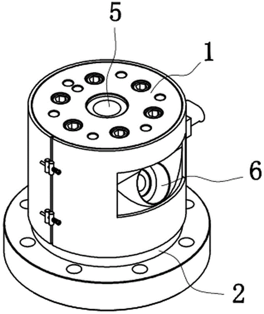
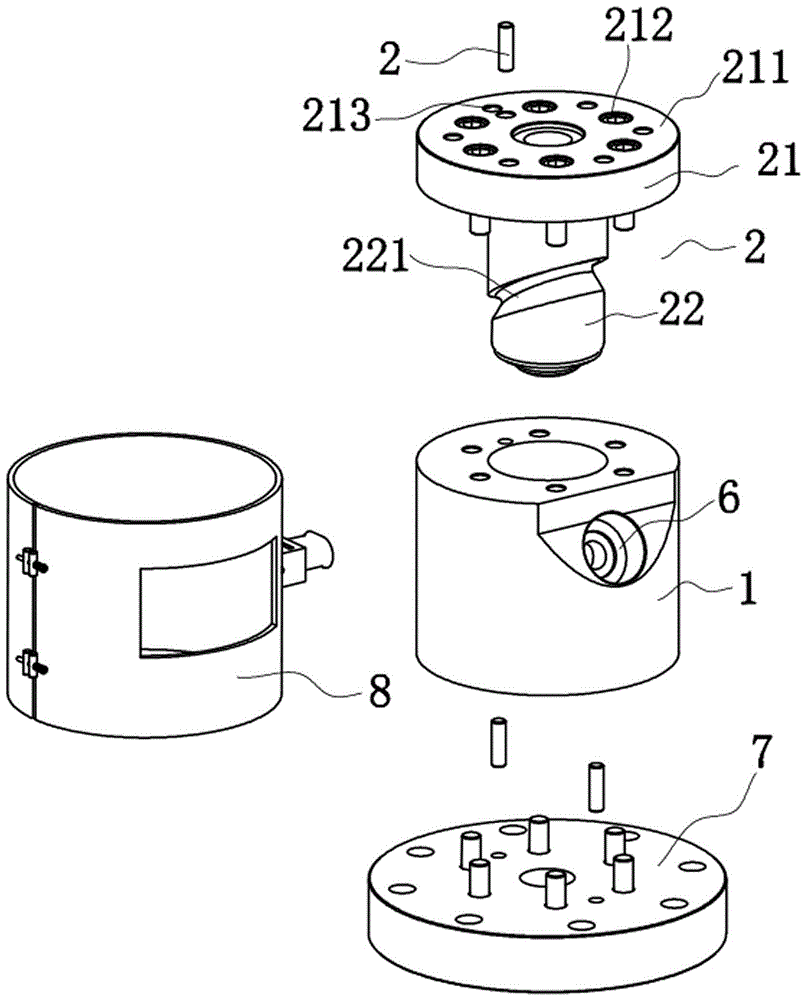
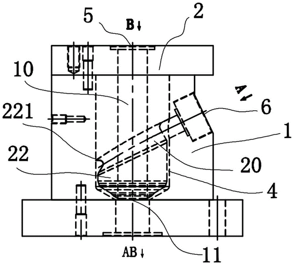
[0019] Such as Figure 1~5 As shown, the circular outlet distributor includes a main body 1 and a shunt mandrel 2, the shunt mandrel 2 is built in the main body 2, one end of the shunt mandrel 2 is a fixed end 21, and the fixed end 21 has a fixed protrusion The edge 211 and the fixing hole 212, the fixed end 21 of the shunt mandrel is matched with the end face of the main body 1 through the positioning pin 3 and the positioning hole 213, and the shunt mandrel 2 and the main body 1 are positioned and then installed into the fixing hole 212 with fixing screws Fasten the two connections.

[0020] Such as figure 2 , 3 As shown, the other end of the splitter mandrel 2 is a cylindrical rod body 22, the front end of the cylindrical rod body 22 is conical. , the auxiliary machine runner groove 221 spirally extends downward toward the outlet. There is a certain gap 4 between t...


PUM


Abstract

The invention discloses a fluid distributor and particularly relates to a distributor with a circular outlet. The distributor comprises a main machine body and a division mandril. One end of the division mandril is a fixed end, and the other end of the division mandril is a columnar rod with an auxiliary machine flow channel groove. The columnar rod is completely embedded into the main machine body. A main machine feed inlet penetrates through the division mandril from the end face of the fixed end to form a main machine feed channel. The main machine body is provided with an auxiliary machine feed inlet which communicates with the auxiliary machine flow channel groove in the division mandril to form an auxiliary machine feed channel. Different fluid separately enters the main machine body from the main machine feed inlet and the auxiliary machine feed inlet and flows through the division mandril and the main machine body to be compounded and converged, and a product of a layered structure is obtained from the circular outlet of the main machine body. The circular outlet of the distributor can be directly in butt joint fit with an extrusion die head, and the layered structure of the fluid cannot be affected. The distributor is compact in overall structure, simple and practical.

Description

technical field [0001] The invention relates to a fluid distributor, in particular to a fluid distributor used in the production of plastic sheets and film extrusion production lines and installed between an extruder and an extrusion die head. Background technique [0002] A common fluid distributor includes a mold body and a shunt mandrel. The shunt mandrel is built into the mold body. The main feed port and the auxiliary feed port are connected to the main flow channel and the auxiliary machine flow channel in the mold. The fluid flows through the main machine. After the channel and the auxiliary machine channel are diverted into their respective layered channels by the diverter mandrel, the thickness of each layer of fluid is adjusted through an adjustment device, such as a swing leaf or a paddle, so as to achieve a layered structure with different thicknesses. Fluids converge from each layered channel and come out from the final outlet of the main channel, and finally ma...

Claims


Application Information

Patent Timeline
Patent Type & Authority Applications(China)
IPC IPC(8): B29C47/70B29C47/06
CPCB29C48/18B29C48/695
Inventor 梁斌
Owner ZHEJIANG JINGCHENG MOLD MASCH CO LTD
Learn More