
An anti-climbing energy-absorbing device

An energy-absorbing device and anti-climbing technology, applied in transportation and packaging, railway car body parts, railway vehicle wheel guards/buffers, etc., can solve the problems of inability to bear vertical loads, poor energy absorption effect, and small energy absorption capacity And other issues

Active Publication Date: 2020-03-10
CRRC CHANGCHUN RAILWAY VEHICLES CO LTD
View PDF8 Cites 0 Cited by
  • Summary
  • Abstract
  • Description
  • Claims
  • Application Information

AI Technical Summary

Problems solved by technology

[0007] The present invention solves the problem that the existing anti-climbing energy-absorbing device has a small energy-absorbing capacity. When a vehicle collides, the anti-climbing teeth are meshed with each other to restrain the generation of a large vertical force, which will cause vertical bending of the energy-absorbing element and change the energy-absorbing element. The deformation mode eventually leads to poor energy absorption effect and cannot bear large longitudinal and vertical loads. A new type of rail transit vehicle is provided with large energy absorption capacity, large vertical stiffness, and can withstand large longitudinal and vertical loads. The load and its combined working conditions can meet the American standard ASME RT-2 2014 and the New York subway technical specification R179 anti-climbing energy-absorbing device

Method used


Image

  • An anti-climbing energy-absorbing device
  • An anti-climbing energy-absorbing device
  • An anti-climbing energy-absorbing device

Examples


Embodiment Construction

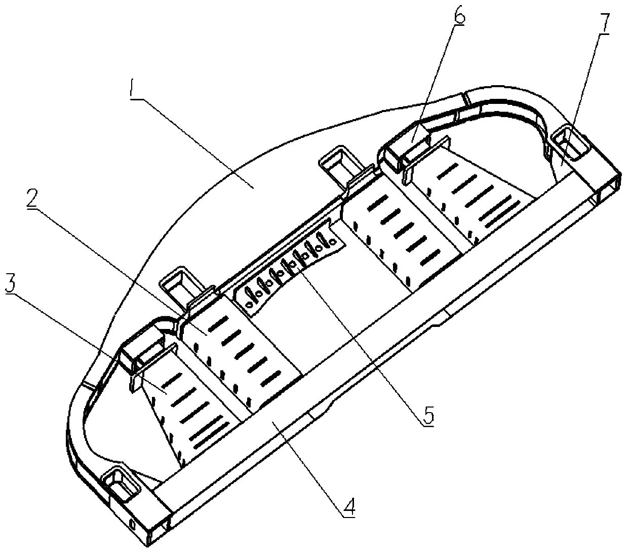
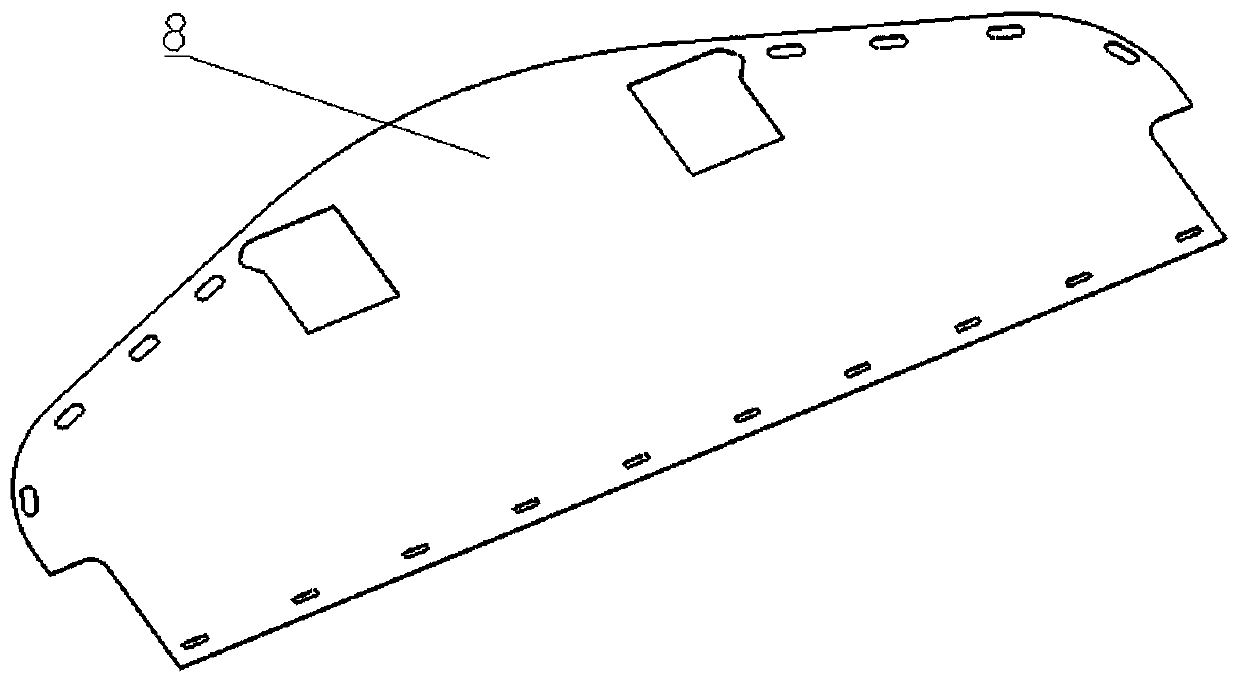
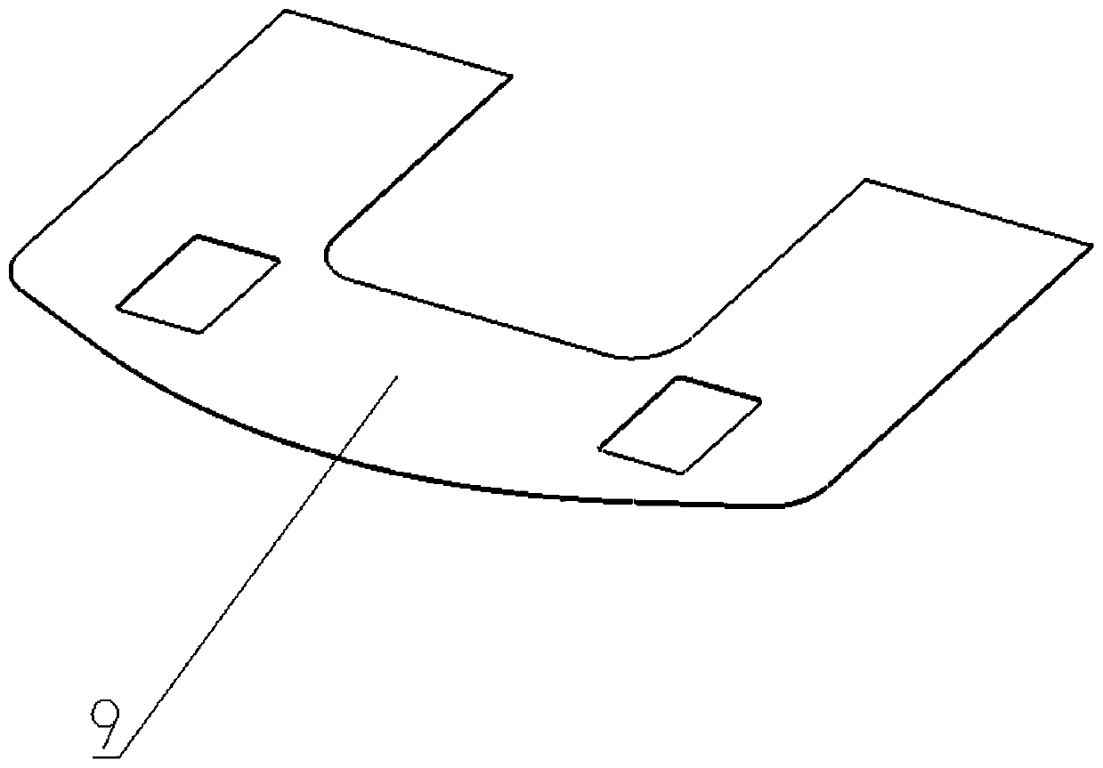
[0035] refer to figure 1 The specific embodiment of the present invention includes an anti-climber module 1, an intermediate composite structure energy-absorbing unit module 2, an energy-absorbing unit module 3 on both sides, an end beam module 4, a coupler installation support seat 5, a pin connection module 6, and an oblique support beam 7 , the upper cover plate 8, the lower cover plate 9; the anti-climber module 1 and the end beam module 4 are welded together to form a closed frame, and are fixed by the inclined support beam 7 at the same time; the energy-absorbing unit module of the intermediate composite structure 2. One end is fixed on the anti-climber module 1, and the other end is fixed on the end beam module 4; one end of the energy-absorbing unit module 3 on both sides is fixed with the anti-climber module 1 through the pin connection module 6, and the other end is fixed on the end beam module 4. On the beam module 4; the upper cover plate 8 and the lower cover plat...


PUM


Abstract

Provided is a novel anti-climbing energy absorbing device. The novel anti-climbing energy absorbing device comprises an anti-climber module, a middle composite structure energy absorbing unit module, a two-sides energy absorbing unit module, an end beam module, a coupler mounting support seat and a pin connecting module; the anti-climber module and the end beam module are welded together, and are fixed by an inclined support beam; one end of the middle composite structure energy absorbing unit module is fixed on the anti-climber module, the other end of the middle composite structure energy absorbing unit module is fixed on the end beam module; one end of the two-side energy absorbing unit module is fixed with the anti-climber module, and the other end is fixed on the end beam module; an upper cover plate and a lower cover plate are connected with the anti-climber module and the end beam module respectively; the coupler mounting support seat is welded with the anti-climber module. In the novel anti-climbing energy absorbing device, the energy absorption capacity is no less than 1.22MJ, the impact force is no greater than 4450kN, vertical compression force of 1424kN can be withstood, and vertical force of 1224kN and lifting force from perpendicular direction of plus or minus 356kN can be withstood at the same time. When a collision accident occurs to a vehicle, the vehicle is prevented from climbing vertically, and the anti-climbing energy absorbing device is involved in absorbing kinetic energy of the collision, the structure of the vehicle body is kept intact, the deceleration passing to passengers is reduced, and passenger casualty is prevented.

Description

technical field [0001] The invention relates to the technical field of rail transit vehicle collision passive safety, in particular to an anti-climbing energy-absorbing device that can simultaneously meet the American standard ASME RT-2 2014 and the New York subway technical specification R179. Background technique [0002] With the rapid development of rail transit, the passive safety of collision, as an important link in the design of modern rail transit vehicles, has attracted more and more attention. [0003] With the rapid development of domestic rail transit, export has become an inevitable trend. The New York subway, which is known for its strict requirements, is a typical representative of the North American market. The collision requirements of New York subway vehicles adopt the American standard ASME RT-2 2014 and technical specification R179, requiring anti-climbing The energy absorption of the energy-absorbing device is not less than 1.22MJ, the average collision...

Claims


Application Information

Patent Timeline
Patent Type & Authority Patents(China)
IPC IPC(8): B61F19/04
CPCB61F19/04
Inventor 刘艳文刘春艳李本怀
Owner CRRC CHANGCHUN RAILWAY VEHICLES CO LTD
Learn More