Supercharge Your Innovation With Domain-Expert AI Agents!

Hydraulic supporting leg for crane

A technology of hydraulic support legs and cranes, which is applied to cranes and other directions, can solve the problems of reducing the stability effect, reducing the contact area, and large size of the supporting legs, and achieves the effects of saving space, increasing the contact area, and having a reasonable device structure.

Inactive Publication Date: 2017-05-24
刘发民
View PDF0 Cites 12 Cited by
  • Summary
  • Abstract
  • Description
  • Claims
  • Application Information

AI Technical Summary

Problems solved by technology

[0002] A crane refers to a multi-action hoisting machine that lifts vertically and transports heavy objects horizontally within a certain range. The working characteristics of the lifting equipment are intermittent movements, that is, the actions of taking, moving, and unloading in a working cycle. The corresponding mechanisms work alternately. The development and use of cranes in the market are becoming more and more extensive. When the crane is working, because the mechanical arm is too long, it will cause the fuselage to be unstable when lifting objects, so it is often necessary to install it on the fuselage. The support legs are used to increase the contact area between the fuselage and the ground, so that the fuselage becomes stable. The traditional crane support legs are large in size and occupy a large area, which is very inconvenient to use. If you choose small support legs, although The footprint is small, but at the same time it also reduces the contact area with the ground and reduces the stabilization effect

Method used


Image

  • Hydraulic supporting leg for crane
  • Hydraulic supporting leg for crane

Examples


Embodiment Construction

[0013] The following will clearly and completely describe the technical solutions in the embodiments of the present invention with reference to the accompanying drawings in the embodiments of the present invention. Obviously, the described embodiments are only some, not all, embodiments of the present invention. Based on the embodiments of the present invention, all other embodiments obtained by persons of ordinary skill in the art without making creative efforts belong to the protection scope of the present invention.

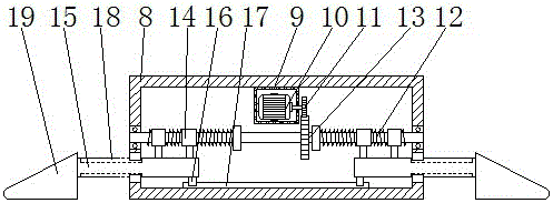
[0014] see Figure 1-2 , the present invention provides a technical solution: a hydraulic support leg of a crane, including a housing 1, a controller 2 is fixedly connected to the left side of the top of the housing 1, and a mounting plate is fixedly connected to the right side of the top and bottom of the housing 1 20 and the mounting plate 20 is provided with mounting holes, through which the support legs can be easily disassembled and installed. The right s...


PUM


Abstract

The invention discloses a hydraulic supporting leg for a crane. The hydraulic supporting leg for the crane comprises a shell. A controller is fixedly connected to the left side of the top of the shell. A first hydraulic rod is fixedly connected to the right side of an inner cavity of the shell. A first supporting rod is arranged in the inner cavity of the shell in a penetrating mode. The right end of the first supporting rod is fixedly connected with the left end of the first hydraulic rod. First sliding blocks are fixedly connected to the right sides of the top and the bottom of the first supporting rod correspondingly. According to the hydraulic supporting leg for the crane, by using the first hydraulic rod and a second hydraulic rod, the supporting leg can stretch and retract flexibly, and the space is saved; meanwhile, by using a threaded rod, the second supporting rod can stretch out of an inner cavity of a base, the contact area between the base and the ground is enlarged, and the stability of a crane body is greatly improved; and the whole hydraulic supporting leg is reasonable in structure, easy to operate and high in practicability.

Description

technical field [0001] The invention relates to the technical field of crane equipment, in particular to a hydraulic support leg of a crane. Background technique [0002] A crane refers to a multi-action hoisting machine that lifts vertically and transports heavy objects horizontally within a certain range. The working characteristics of lifting equipment are intermittent movements, that is, the actions of taking, moving, and unloading in a working cycle. The corresponding mechanisms work alternately. The development and use of cranes in the market are becoming more and more extensive. When the crane is working, because the mechanical arm is too long, it will cause the fuselage to be unstable when lifting objects, so it is often necessary to install on the fuselage. The support legs are used to increase the contact area between the fuselage and the ground, so that the fuselage becomes stable. The traditional crane support legs are large in size and occupy a large area, which...

Claims


Application Information

Patent Timeline
Patent Type & Authority Applications(China)
IPC IPC(8): B66C23/80
CPCB66C23/80
Inventor 刘发民
Owner 刘发民
Features
  • R&D
  • Intellectual Property
  • Life Sciences
  • Materials
  • Tech Scout
  • Unparalleled Data Quality
  • Higher Quality Content
  • 60% Fewer Hallucinations
Learn More