
Entrained bed reactor for the production of synthesis gas

A synthesis gas and reactor technology, which is applied in the manufacture of combustible gas, gasification process, granular/powder fuel gasification, etc., can solve the problems of high cost and lack of protection, and achieve simplified structural structure, easy access, The effect of improving accessibility

Active Publication Date: 2021-01-08
CHOREN INDTECHN
View PDF10 Cites 0 Cited by
  • Summary
  • Abstract
  • Description
  • Claims
  • Application Information

AI Technical Summary

Problems solved by technology

[0016] The disadvantage of these solutions is that they are cost-intensive and only form separate measures for inhibiting corrosion damage, which do not achieve complete protection

Method used


Image

  • Entrained bed reactor for the production of synthesis gas

Examples


Embodiment Construction

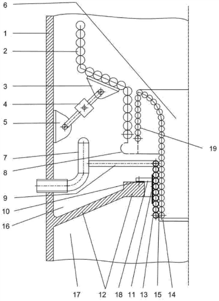
[0029]An entrained-bed reactor for the production of synthesis gas from carbonaceous fuels according to the downstream principle initially consists of an outer, pressure-containing jacket (reactor wall 1 ). Arranged in the upper part of the reactor is a reaction chamber in which crude gases and residues form at high temperature and high pressure. To protect the pressurized reactor wall 1, the reaction chamber is delimited by a cylindrical cooling screen 2, which has a conical lower section and consists of coils through which cooling water flows, which are gas-tight connected to each other.

[0030] Between the reactor wall 1 and the cooling screen 2 there is an annular space 16 which can be purged with an inert gas which can be introduced from the outside in order to protect the reactor wall 1 and the cooling screen 2 from being caused by Corrosion caused by stray reactive gases.

[0031] A quenching space 17 adjoins the reaction chamber in the direction of flow of the raw g...


PUM


Abstract

The invention relates to an entrained flow bed reactor for producing synthetic gas. The invention is based on the object of providing structural improvement in a residue discharge area. The improvement overcomes the aforementioned disadvantages of the prior art and ensures an effective long-term protection of all reactor components in the area in the residue discharge area. The object is achieved by a horizontal intermediate floor which closes a quench chamber upwards, the intermediate floor extending at the level of the residue discharge body from a reactor wall to the slag outlet body and being connected to the reactor wall and the residue discharge body in a gas-tight manner by a gas-tight connection between a cooling screen and the residue discharge body and through cooling water feeding channels and cooling water discharging channels in the reactor. The cooling water feeding and discharging channels are associated with the cooling screen and the residue discharge body, are guided into the reactor above an intermediate floor, and are connected above the intermediate floor with coils of the cooling screen and the residue discharge body.

Description

technical field [0001] The present invention relates to an entrained bed reactor for the production of synthesis gas from carbonaceous fuels. Background technique [0002] An entrained bed reactor of this type generally comprises an outer, pressurized reactor wall enclosing a reaction chamber for the formation of crude gas and residue and a cylindrical cooling screen which keeps the The reaction chamber is delimited by the reactor wall. The cooling screen is formed by coils through which cooling water can flow and has a conical lower section. Between the cooling screen and the reactor wall there is an annular space which can be purged with an inert gas. The entrained bed reactor also has a quench space, which is connected to the reaction chamber and serves to cool the raw gas by bringing it into contact with water. The conical lower section of the cooling screen is continued by a funnel-shaped body which surrounds a concentric opening between the reactor wall and the quen...

Claims


Application Information

Patent Timeline
Patent Type & Authority Patents(China)
IPC IPC(8): C10J3/48C10J3/52C10J3/84
CPCC10J3/485C10J3/526C10J3/84C10J3/845C10J2300/1603C10J3/48
Inventor 法比安·艾佐尔德
Owner CHOREN INDTECHN
Learn More